- Page 1 and 2:
Evangelism After Christendom: The T
- Page 3 and 4: LPLWHG:DUUDQW\Copper Mountain Netwo
- Page 6 and 7: 8QLWHG6WDWHV)&&3DUW7HOHFRPPXQLFDWLR
- Page 8 and 9: YLLL&RSSHU(GJH,QVWDOODWLRQDQG2SHUDW
- Page 10 and 11: Optional Equipment . . . . . . . .
- Page 12 and 13: DSL IMUX . . . . . . . . . . . . .
- Page 14 and 15: Alarms. . . . . . . . . . . . . . .
- Page 16 and 17: Appendix E CPE Inside Wiring. . . .
- Page 18 and 19: IDSL Loop with Multiple Network Ele
- Page 20 and 21: 5HYLVLRQ+LVWRU\Rev Rev Date Summary
- Page 22 and 23: &RQFHSWRI2SHUDWLRQThe following ill
- Page 24 and 25: 7KLUG3DUW\&XVWRPHU3UHPLVH(TXLSPHQW&
- Page 26 and 27: 6\VWHP&RQWURO0RGXOHV• SCM-1 and S
- Page 28 and 29: 6RIWZDUH)HDWXUHV'6//LQN3URWRFROV•
- Page 30 and 31: 3URGXFW&HUWLILFDWLRQLQ1RUWK$PHULFD
- Page 32 and 33: &RSSHU(GJH,QVWDOODWLRQDQG2SHUDWLQJ*
- Page 34 and 35: 6LWH3UHSDUDWLRQBefore installing th
- Page 36 and 37: • One DSL Connector Cable—10 fe
- Page 38 and 39: System SoftwareIn addition to the c
- Page 40 and 41: PORTSTATUSMONRECEIVEMONTRANSMITMODU
- Page 42 and 43: -48 VRTN-48 VRTNAlso, just below an
- Page 44 and 45: Ground the CE150 ChassisWhen operat
- Page 46 and 47: '6//LQN&RQQHFWLRQVThe illustrations
- Page 48 and 49: )URQW3DQHO&RQQHFWLRQVThis section d
- Page 50 and 51: 1 2 7 (We recommend that you do not
- Page 52 and 53: 6\VWHP&RQWURO0RGXOHThe System Contr
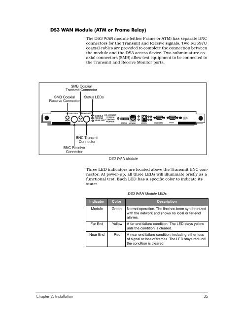
- Page 56 and 57: '6:$10RGXOH4XDG7The DS1 WAN module
- Page 58 and 59: Power-Up LED SequencHBefore you con
- Page 60 and 61: data traffic. The Network indicator
- Page 62 and 63: &RQQHFWWKH3RZHUNow that you underst
- Page 64 and 65: 6\VWHP&RQILJXUDWLRQ*XLGHOLQHVConfig
- Page 66 and 67: &RSSHU&UDIW/LQH(GLWRUCommand string
- Page 68 and 69: • A PII such as 1.4.24 identifies
- Page 70 and 71: You can enter multiple Get commands
- Page 72 and 73: ,QLWLDO&RQILJXUDWLRQWith the CE150
- Page 74 and 75: Management by a Radius ServerIf you
- Page 76 and 77: To create the Private community nam
- Page 78 and 79: 4. In this example of an interface
- Page 80 and 81: &RSSHU(GJH,QVWDOODWLRQDQG2SHUDWLQJ*
- Page 82 and 83: &RQILJXULQJ'6//LQNVIRU1HWZRUN0RGHOV
- Page 84 and 85: CMCPCompatible = NoEncapsulationTyp
- Page 86 and 87: When many DSL links comprise a virt
- Page 88 and 89: 15. Log out of the Command Line Int
- Page 90 and 91: Each CopperVPN group is separate an
- Page 92 and 93: &URVV&RQQHFW1HWPRGHOThe Cross-Conne
- Page 94 and 95: FRF.5 Forwarding ModeThis translati
- Page 96 and 97: RFC-1973 is configured on the port
- Page 98 and 99: +LJK'HQVLW\,QWHUQHW$FFHVV+',$1HWPRG
- Page 100 and 101: • A unique circuit identifier is
- Page 102 and 103: To configure the CE150 to act as a
- Page 104 and 105:
When the netmodel is IP, the CPE or
- Page 106 and 107:
2. The CE150 forwards the request t
- Page 108 and 109:
2$0)DXOW0DQDJHPHQWIRU$70:$1/LQNVThe
- Page 110 and 111:
&RQILJXULQJWKH2$0)XQFWLRQTo configu
- Page 112 and 113:
Manual Loopback RequestsThe manual
- Page 114 and 115:
Every source of IP packets can be i
- Page 116 and 117:
)LOWHU&ULWHULDEach IP filter includ
- Page 118 and 119:
SrcMaskSrcAdrsDstMaskDstAdrsIpProto
- Page 120 and 121:
&RQILJXULQJDQ,08;%XQGOHIn general,
- Page 122 and 123:
'6/9RLFHDQG'DWD6HUYLFHIn addition t
- Page 124 and 125:
5DGLXV$XWKHQWLFDWLRQEnhanced system
- Page 126 and 127:
&RQILJXULQJ5DGLXV6HUYHUVIRU&RSSHU(G
- Page 128 and 129:
6DYLQJ9DOXHVHere are the proprietar
- Page 130 and 131:
&RQILJXULQJ%DFNXSEven with a modest
- Page 132 and 133:
CRAFT> set cmmaintcmd [configrestor
- Page 134 and 135:
)HDWXUHV'6)UDPH5HOD\0RGXOHNo specia
- Page 136 and 137:
&RQILJXULQJ&(1HWZRUN,QWHUIDFHVYou c
- Page 138 and 139:
&RQILJXULQJ)XOO,3'6//LQNVYou config
- Page 140 and 141:
,33ROLF\2YHU(WKHUQHW1 2 7 (Performa
- Page 142 and 143:
&RQILJXULQJ3RUWVIRU9:$12YHU(WKHUQHW
- Page 144 and 145:
&RQILJXULQJ:$19&VVirtual Circuits,
- Page 146 and 147:
&RQILJXULQJ'6)UDPH5HOD\To establish
- Page 148 and 149:
As a practical matter, however, a u
- Page 150 and 151:
&RQILJXULQJ'6$70The CE150 provides
- Page 152 and 153:
&RQILJXULQJ4XDG7)UDPH5HOD\The Quad
- Page 154 and 155:
&RSSHU(GJH,QVWDOODWLRQDQG2SHUDWLQJ*
- Page 156 and 157:
2YHUYLHZRI9R'6/In delivering digiti
- Page 158 and 159:
'XDO3DWKZD\VRQDQ,$'The CopperRocket
- Page 160 and 161:
To simplify the process of addressi
- Page 162 and 163:
3. Two IP Addressing Groups:The two
- Page 164 and 165:
3ODQQLQJ0XOWLSOH+RVWVRQ+',$Although
- Page 166 and 167:
&RQILJXULQJ+',$'DWDDQG9RLFH6XEQHWVT
- Page 168 and 169:
3. Set the VC for data on the WAN p
- Page 170 and 171:
7. Set the VC for data on the first
- Page 172 and 173:
10. Set the DSL port (1.4.13) for t
- Page 174 and 175:
13. If the IP addresses are already
- Page 176 and 177:
16. Set the addressing for the seco
- Page 178 and 179:
2YHUYLHZRI*GPWDQG*OLWHBoth the G.dm
- Page 180 and 181:
3ODQQLQJWKH*GPWDQG*OLWH1HWZRUNAltho
- Page 182 and 183:
&RQILJXULQJWKH*GPWDQG*OLWH'DWD1HWZR
- Page 184 and 185:
3. Set the VC on the DSL port. Use
- Page 186 and 187:
,31HWPRGHOIn the IP netmodel, the e
- Page 188 and 189:
3. Set the VC on the DSL port. Use
- Page 190 and 191:
&RSSHU(GJH,QVWDOODWLRQDQG2SHUDWLQJ*
- Page 192 and 193:
&('LDJQRVWLF)HDWXUHVThe CE150 inclu
- Page 194 and 195:
1 2 7 (A green-lit Ethernet LED is
- Page 196 and 197:
• Yellow—A far-end failure cond
- Page 198 and 199:
5HVRXUFH,GHQWLILFDWLRQThe resource
- Page 200 and 201:
• CPE-IDSL• Netopia-SDSL• CPE
- Page 202 and 203:
Alarm LogAlarm messages are written
- Page 204 and 205:
7UDSVIn the CE150, every internal e
- Page 206 and 207:
([DPSOH$ODUPVDQG(YHQWVElog DisplayT
- Page 208 and 209:
6DYH&RQILJXUDWLRQ)DLOXUHIf the syst
- Page 210 and 211:
'+&33UREOHPVThe proper functioning
- Page 212 and 213:
The IDSL Module includes a CPE moni
- Page 214 and 215:
'6/RRSEDFNVFor DS3 boards, either A
- Page 216 and 217:
7. At the CE150 console, wait five
- Page 218 and 219:
,08;&RQILJXUDWLRQ,VVXHVFor setting
- Page 220 and 221:
3UREOHPVGXULQJ&3(7UDLQLQJIf there i
- Page 222 and 223:
6\VORJIn certain situations, it can
- Page 224 and 225:
&3(0HVVDJH/RJ7DEOHIf you need to pe
- Page 226 and 227:
10. Display the message entries in
- Page 228 and 229:
5HVWDUW2SWLRQVAs mentioned elsewher
- Page 230 and 231:
6\VWHP&RQILJXUDWLRQIf you suspect t
- Page 232 and 233:
7. When the module is seated in the
- Page 234 and 235:
'6//LQH0RGXOHVReplacement of any DS
- Page 236 and 237:
&RSSHU0RXQWDLQ6HUYLFHDQG6XSSRUWThe
- Page 238 and 239:
'6/3RUW(QFDSVXODWLRQV1483 FUNI(Ethe
- Page 240 and 241:
1HWPRGHOV(QFDSVXODWLRQVDQG7UDQVODWL
- Page 242 and 243:
:$13RUW(QFDSVXODWLRQVCurrently, WAN
- Page 244 and 245:
&RSSHU(GJH,QVWDOODWLRQDQG2SHUDWLQJ*
- Page 246 and 247:
In general, the netmodels behave qu
- Page 248 and 249:
7KHFP,IDFH7DEOHAt the center of all
- Page 250 and 251:
IpAddr(Read/Write)NetMask(Read/Writ
- Page 252 and 253:
Policy-to-Ethernet IP RoutingYou ca
- Page 254 and 255:
&RSSHU9311HWPRGHOThis section assum
- Page 256 and 257:
&RSSHU(GJH,QVWDOODWLRQDQG2SHUDWLQJ*
- Page 258 and 259:
$ODUPVType Severity DescriptionAtmV
- Page 260 and 261:
Type Severity DescriptionIDSLTiming
- Page 262 and 263:
$ODUP&OHDULQJ1RWLILFDWLRQVType Seve
- Page 264 and 265:
Type Severity DescriptionLinkUp Not
- Page 266 and 267:
Type Severity DescriptionFallingThr
- Page 268 and 269:
&RSSHU(GJH,QVWDOODWLRQDQG2SHUDWLQJ*
- Page 270 and 271:
6RIWZDUH8SJUDGH2YHUYLHZWhile specif
- Page 272 and 273:
8SJUDGHWKH&(6RIWZDUHThis section pr
- Page 274 and 275:
4. Rename the ce200- directory to c
- Page 276 and 277:
226 Transfer complete14509 bytes se
- Page 278 and 279:
&RSSHU(GJH,QVWDOODWLRQDQG2SHUDWLQJ*
- Page 280 and 281:
9LHZWKH&RPSUHVVHG&RQILJXUDWLRQ)LOHT
- Page 282 and 283:
8SJUDGLQJ0XOWLSOH&3(VTo upgrade or
- Page 284 and 285:
&RSSHU(GJH,QVWDOODWLRQDQG2SHUDWLQJ*
- Page 286 and 287:
Inside Wiring for xDSL CPE withCopp
- Page 288 and 289:
CE150, CE200 CopperEdge 150 and Cop
- Page 290 and 291:
LLAN Local Area Network. A short di
- Page 292 and 293:
VP Virtual Path. A unidirectional A
- Page 294 and 295:
SCM-3, 34ANSI T1.606 Addendum 1 FR
- Page 296 and 297:
Diagnostic port, 29, 33Ethernet por
- Page 298 and 299:
RFC-2225 network protocol, 8RFC-239
- Page 300 and 301:
&RSSHU(GJH,QVWDOODWLRQDQG2SHUDWLQJ*
- Page 303:
Sheet ______ of _______WAN Port Con