II - DCE FEL ČVUT v Praze
II - DCE FEL ČVUT v Praze
II - DCE FEL ČVUT v Praze
Create successful ePaper yourself
Turn your PDF publications into a flip-book with our unique Google optimized e-Paper software.
Contents<br />
Tables<br />
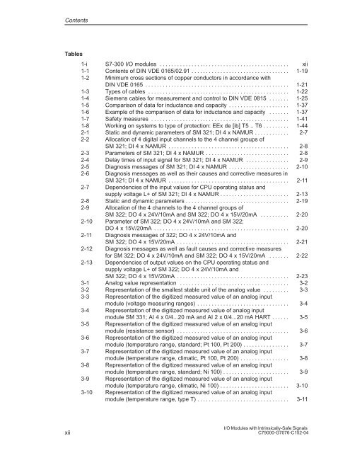
1-i S7-300 I/O modules . . . . . . . . . . . . . . . . . . . . . . . . . . . . . . . . . . . . . . . . . . . . . xii<br />
1-1 Contents of DIN VDE 0165/02.91 . . . . . . . . . . . . . . . . . . . . . . . . . . . . . . . . . . 1-19<br />
1-2 Minimum cross sections of copper conductors in accordance with<br />
DIN VDE 0165 . . . . . . . . . . . . . . . . . . . . . . . . . . . . . . . . . . . . . . . . . . . . . . . . . . 1-21<br />
1-3 Types of cables . . . . . . . . . . . . . . . . . . . . . . . . . . . . . . . . . . . . . . . . . . . . . . . . . 1-22<br />
1-4 Siemens cables for measurement and control to DIN VDE 0815 . . . . . . . 1-25<br />
1-5 Comparison of data for inductance and capacity . . . . . . . . . . . . . . . . . . . . . 1-37<br />
1-6 Example of the comparison of data for inductance and capacity . . . . . . . 1-37<br />
1-7 Safety measures . . . . . . . . . . . . . . . . . . . . . . . . . . . . . . . . . . . . . . . . . . . . . . . . 1-41<br />
1-8 Working on systems to type of protection: EEx de [ib] T5 .. T6 . . . . . . . . . 1-44<br />
2-1 Static and dynamic parameters of SM 321; DI 4 x NAMUR . . . . . . . . . . . . 2-7<br />
2-2 Allocation of 4 digital input channels to the 4 channel groups of<br />
SM 321; DI 4 x NAMUR . . . . . . . . . . . . . . . . . . . . . . . . . . . . . . . . . . . . . . . . . . 2-8<br />
2-3 Parameters of SM 321; DI 4 x NAMUR . . . . . . . . . . . . . . . . . . . . . . . . . . . . . 2-8<br />
2-4 Delay times of input signal for SM 321; DI 4 x NAMUR . . . . . . . . . . . . . . . 2-9<br />
2-5 Diagnosis messages of SM 321; DI 4 x NAMUR . . . . . . . . . . . . . . . . . . . . . 2-10<br />
2-6 Diagnosis messages as well as their causes and corrective measures in<br />
SM 321; DI 4 x NAMUR . . . . . . . . . . . . . . . . . . . . . . . . . . . . . . . . . . . . . . . . . . 2-11<br />
2-7 Dependencies of the input values for CPU operating status and<br />
supply voltage L+ of SM 321; DI 4 x NAMUR . . . . . . . . . . . . . . . . . . . . . . . . 2-13<br />
2-8 Static and dynamic parameters . . . . . . . . . . . . . . . . . . . . . . . . . . . . . . . . . . . . 2-19<br />
2-9 Allocation of the 4 channels to the 4 channel groups of<br />
SM 322; DO 4 x 24V/10mA and SM 322; DO 4 x 15V/20mA . . . . . . . . . . 2-20<br />
2-10 Parameter of SM 322; DO 4 x 24V/10mA and SM 322;<br />
DO 4 x 15V/20mA . . . . . . . . . . . . . . . . . . . . . . . . . . . . . . . . . . . . . . . . . . . . . . . 2-20<br />
2-11 Diagnosis messages of 322; DO 4 x 24V/10mA and<br />
SM 322; DO 4 x 15V/20mA . . . . . . . . . . . . . . . . . . . . . . . . . . . . . . . . . . . . . . . 2-21<br />
2-12 Diagnosis messages as well as fault causes and corrective measures<br />
for SM 322; DO 4 x 24V/10mA and SM 322; DO 4 x 15V/20mA . . . . . . . 2-22<br />
2-13 Dependencies of output values on the CPU operating status and<br />
supply voltage L+ of SM 322; DO 4 x 24V/10mA and<br />
SM 322; DO 4 x 15V/20mA . . . . . . . . . . . . . . . . . . . . . . . . . . . . . . . . . . . . . . . 2-23<br />
3-1 Analog value representation . . . . . . . . . . . . . . . . . . . . . . . . . . . . . . . . . . . . . . 3-2<br />
3-2 Representation of the smallest stable unit of the analog value . . . . . . . . . 3-3<br />
3-3 Representation of the digitized measured value of an analog input<br />
module (voltage measuring ranges) . . . . . . . . . . . . . . . . . . . . . . . . . . . . . . . . 3-4<br />
3-4 Representation of the digitized measured value of analog input<br />
module SM 331; AI 4 x 0/4...20 mA and AI 2 x 0/4...20 mA HART . . . . . . 3-5<br />
3-5 Representation of the digitized measured value of an analog input<br />
module (resistance sensor) . . . . . . . . . . . . . . . . . . . . . . . . . . . . . . . . . . . . . . . 3-6<br />
3-6 Representation of the digitized measured value of an analog input<br />
module (temperature range, standard; Pt 100, Pt 200) . . . . . . . . . . . . . . . . 3-7<br />
3-7 Representation of the digitized measured value of an analog input<br />
module (temperature range, climatic, Pt 100, Pt 200) . . . . . . . . . . . . . . . . . 3-8<br />
3-8 Representation of the digitized measured value of an analog input<br />
module (temperature range, standard; Ni 100) . . . . . . . . . . . . . . . . . . . . . . . 3-9<br />
3-9 Representation of the digitized measured value of an analog input<br />
module (temperature range, climatic, Ni 100) . . . . . . . . . . . . . . . . . . . . . . . . 3-10<br />
3-10 Representation of the digitized measured value of an analog input<br />
module (temperature range, type T) . . . . . . . . . . . . . . . . . . . . . . . . . . . . . . . . 3-11<br />
xii<br />
I/O Modules with Intrinsically-Safe Signals<br />
C79000-G7076-C152-04


