

II - DCE FEL ČVUT v Praze
II - DCE FEL ČVUT v Praze
II - DCE FEL ČVUT v Praze

Create successful ePaper yourself
Turn your PDF publications into a flip-book with our unique Google optimized e-Paper software.
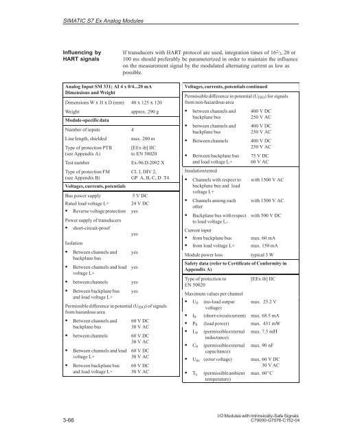
SIMATIC S7 Ex Analog Modules<br />
Influencing by<br />
HART signals<br />
Analog Input SM 331; AI 4 x 0/4...20 mA<br />
Dimensions and Weight<br />
Dimensions W x H x D (mm) 40 x 125 x 120<br />
Weight approx. 290 g<br />
Module-specific data<br />
Number of inputs 4<br />
Line length, shielded max. 200 m<br />
Type of protection PTB<br />
(see Appendix A)<br />
3-66<br />
If transducers with HART protocol are used, integration times of 16 2 /3, 20 or<br />
100 ms should preferably be parameterized in order to maintain the influence<br />
on the measurement signal by the modulated alternating current as low as<br />
possible.<br />
[EEx ib] <strong>II</strong>C<br />
to EN 50020<br />
Test number Ex-96.D.2092 X<br />
Type of protection FM<br />
(see Appendix B)<br />
Voltages, currents, potentials<br />
Bus power supply<br />
Rated load voltage L+<br />
Reverse voltage protection<br />
Power supply of transducers<br />
short-circuit-proof<br />
CL I, DIV 2,<br />
GP A, B, C, D T4<br />
5 V DC<br />
24 V DC<br />
yes<br />
yes<br />
Isolation<br />
Between channels and<br />
backplane bus<br />
yes<br />
Between channels and load<br />
voltage L+<br />
yes<br />
between channels yes<br />
Between backplane bus<br />
and load voltage L+<br />
yes<br />
Permissible difference in potential (UISO) of signals<br />
from hazardous area<br />
Between channels and<br />
backplane bus<br />
60 V DC<br />
30 V AC<br />
between channels 60 V DC<br />
30 V AC<br />
Between channels and load<br />
voltage L+<br />
Between backplane bus<br />
and load voltage L+<br />
60 V DC<br />
30 V AC<br />
60 V DC<br />
30 V AC<br />
Voltages, currents, potentials continued<br />
Permissible difference in potential (UISO) for signals<br />
from non-hazardous area<br />
between channels and<br />
backplane bus<br />
between channels and<br />
backplane bus<br />
400 V DC<br />
250 V AC<br />
400 V DC<br />
250 V AC<br />
Between channels 400 V DC<br />
250 V AC<br />
Between backplane bus<br />
and load voltage L+<br />
Insulation tested<br />
Channels with respect to<br />
backplane bus and load<br />
voltage L+<br />
Channels among each<br />
other<br />
Backplane bus with respect<br />
to load voltage L+<br />
Current input<br />
from backplane bus<br />
from load voltage L+<br />
75 V DC<br />
60 V AC<br />
with 1500 V AC<br />
with 1500 V AC<br />
with 500 V DC<br />
max. 60 mA<br />
max. 150 mA<br />
Module power loss typical 3 W<br />
Safety data (refer to Certificate of Conformity in<br />
Appendix A)<br />
Type of protection to<br />
EN 50020<br />
Maximum values per channel<br />
U0 (no-load output<br />
voltage)<br />
[EEx ib] <strong>II</strong>C<br />
max. 25.2 V<br />
I0 (short-circuit current) max. 68.5 mA<br />
P0 (load power) max. 431 mW<br />
L0 (permissible external<br />
inductance)<br />
max. 7.5 m<br />
C0 (permissible external<br />
capacitance)<br />
max. 90 nF<br />
Um (error voltage) max. 60 V DC<br />
30 V AC<br />
Ta (permissible ambient<br />
temperature)<br />
max. 60C<br />
I/O Modules with Intrinsically-Safe Signals<br />
C79000-G7076-C152-04


