- Page 1 and 2:
SIMATIC S7-300, M7-300, ET 200M Aut
- Page 3 and 4:
Preface Purpose of the manual Conte
- Page 5 and 6:
Usage and configuration Usage and c
- Page 7 and 8:
Contents Preface . . . . . . . . .
- Page 9 and 10:
4.6 HART Analog Input Module SM 331
- Page 11 and 12:
3-13 Connection of loads to a curre
- Page 13 and 14:
3-11 Representation of the digitize
- Page 15 and 16:
Mechanical Configuration of an Auto
- Page 17 and 18:
Minimum thread measure Mechanical C
- Page 19 and 20:
Replacing Ex I/O modules Mechanical
- Page 21 and 22:
Wire end ferrule Fig. 1-2 Installin
- Page 23 and 24:
1.3 Configuration of an S7-300 with
- Page 25 and 26:
1.4 Configuration of an M7-300 with
- Page 27 and 28:
1.6 Equipotential Bonding in System
- Page 29 and 30:
Main equipotential bonding Addition
- Page 31 and 32:
Mechanical Configuration of an Auto
- Page 33 and 34:
Mechanical Configuration of an Auto
- Page 35 and 36:
1.7.4 Selecting Cables and Lines in
- Page 37 and 38:
Type designations for lines in acco
- Page 39 and 40:
Table 1-4 Siemens cables for measur
- Page 41 and 42:
Mechanical Configuration of an Auto
- Page 43 and 44:
Shielding of intrinsically safe sig
- Page 45 and 46:
1.8.3 Measures to Counteract Interf
- Page 47 and 48:
Mechanical Configuration of an Auto
- Page 49 and 50:
Mechanical Configuration of an Auto
- Page 51 and 52:
Mechanical Configuration of an Auto
- Page 53 and 54:
Mechanical Configuration of an Auto
- Page 55 and 56:
Table 1-7 Safety measures Mechanica
- Page 57 and 58:
Housing Cables Terminals Protective
- Page 59 and 60:
Table 1-8 Working on systems to typ
- Page 61 and 62:
SIMATIC S7 Ex Digital Modules In th
- Page 63 and 64:
Wiring diagram SM 321 DI 4 x NAMUR
- Page 65 and 66:
Digital input SM 321; DI 4 x NAMUR
- Page 67 and 68:
Parameterization Default settings C
- Page 69 and 70:
Input delay Diagnostics Parameteriz
- Page 71 and 72:
Errors and corrective measures I/O
- Page 73 and 74:
Influence of supply voltage and ope
- Page 75 and 76:
Wiring diagram Notes on intrinsical
- Page 77 and 78:
Digital output SM 322; DO 4 x 24V/1
- Page 79 and 80:
Parameterization Default settings C
- Page 81 and 82:
Diagnostic evaluation Diagnostics o
- Page 83 and 84:
Interrupts Parameterizing interrupt
- Page 85 and 86:
Block diagram S7-300 Backplane bus
- Page 87 and 88:
Safety data (refer to Certificate o
- Page 89 and 90:
SIMATIC S7 Ex Analog Modules In thi
- Page 91 and 92:
3.1.2 Analog Representation for Mea
- Page 93 and 94:
Current measuring ranges I/O Module
- Page 95 and 96:
Temperature range, standard, Pt 100
- Page 97 and 98:
Temperature range, standard, Ni 100
- Page 99 and 100:
DIN IEC 584 Temperature range type
- Page 101 and 102: Temperature range type E I/O Module
- Page 103 and 104: Temperature range type L I/O Module
- Page 105 and 106: Temperature range type N I/O Module
- Page 107 and 108: Temperature range type S I/O Module
- Page 109 and 110: 3.1.3 Analog Value Representation f
- Page 111 and 112: Abbreviations Insulated measured va
- Page 113 and 114: 3.3 Connection of Thermocouples, Vo
- Page 115 and 116: Internal compensation Thermocouple
- Page 117 and 118: Thermocouples with direct looping-i
- Page 119 and 120: Thermocouples with internal compens
- Page 121 and 122: 3.3.3 Connection of Resistance Ther
- Page 123 and 124: I/O Modules with Intrinsically-Safe
- Page 125 and 126: Connecting loads to a current outpu
- Page 127 and 128: I/O Modules with Intrinsically-Safe
- Page 129 and 130: 3.6.3 Parameters of Analog Modules
- Page 131 and 132: Table 3-22 Parameters of the analog
- Page 133 and 134: 3.6.4 Diagnostics of Analog Modules
- Page 135 and 136: Table 3-25 Diagnostic messages of a
- Page 137 and 138: Faults and corrective measures I/O
- Page 139 and 140: 3.6.6 Characteristics of Analog Mod
- Page 141 and 142: Influence of faults I/O Modules wit
- Page 143 and 144: Wiring diagram SM 33 1 AI 8 xTC / 4
- Page 145 and 146: Special feature of resistant measur
- Page 147 and 148: Analog Input SM 331; AI 8 x TC/4 x
- Page 149 and 150: Error limits of analog inputs for t
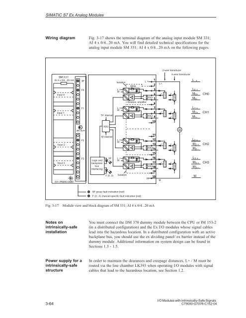
- Page 151: 3.8 Analog Input Module SM 331; AI
- Page 155 and 156: Analog value formation Measuring pr
- Page 157 and 158: Wiring diagram SM 3 32 AO 4 x 0/4..
- Page 159 and 160: Analog output Output ranges I/O Mod
- Page 161 and 162: Interference rejection, error limit
- Page 163 and 164: SIMATIC S7 HART Analog Modules In t
- Page 165 and 166: 4.2 Introduction to HART Introducti
- Page 167 and 168: Examples of HART parameters Example
- Page 169 and 170: 4.3 Guidelines for Installation, St
- Page 171 and 172: Modifying the parameters of the fie
- Page 173 and 174: 4.4 Parameters of HART Analog Modul
- Page 175 and 176: 4.5 Diagnostics and Interrupts of H
- Page 177 and 178: 4.6 HART Analog Input Module SM 331
- Page 179 and 180: Wiring diagram SM 3 31 AI 2 x 0/4..
- Page 181 and 182: Analog value formation Measuring pr
- Page 183 and 184: Default settings Wire break monitor
- Page 185 and 186: SM 332; AO 2 x 0/4...20mA HART Dime
- Page 187 and 188: 4.8 Data Record Interface and User
- Page 189 and 190: Structure of the parameter data rec
- Page 191 and 192: Diagnostic data: data record 1 Note
- Page 193 and 194: Structure of command data record No
- Page 195 and 196: Table 4-13 HART group error display
- Page 197 and 198: Structure of the diagnostic data re
- Page 199 and 200: 4.8.6 User Data Interface Input Are
- Page 201 and 202: Certificates of Conformity In this
- Page 203 and 204:
I/O Modules with Intrinsically-Safe
- Page 205 and 206:
A.1.1 ASEV Certificate/Switzerland
- Page 207 and 208:
I/O Modules with Intrinsically-Safe
- Page 209 and 210:
A.2 Certificate of Conformity for D
- Page 211 and 212:
A.2.1 ASEV Certificate/Switzerland
- Page 213 and 214:
I/O Modules with Intrinsically-Safe
- Page 215 and 216:
A.3 Certificate of Conformity for D
- Page 217 and 218:
A.3.1 ASEV Certificate/Switzerland
- Page 219 and 220:
I/O Modules with Intrinsically-Safe
- Page 221 and 222:
I/O Modules with Intrinsically-Safe
- Page 223 and 224:
I/O Modules with Intrinsically-Safe
- Page 225 and 226:
I/O Modules with Intrinsically-Safe
- Page 227 and 228:
I/O Modules with Intrinsically-Safe
- Page 229 and 230:
I/O Modules with Intrinsically-Safe
- Page 231 and 232:
I/O Modules with Intrinsically-Safe
- Page 233 and 234:
I/O Modules with Intrinsically-Safe
- Page 235 and 236:
I/O Modules with Intrinsically-Safe
- Page 237 and 238:
A.6.2 ASEV Certificate/Switzerland
- Page 239 and 240:
I/O Modules with Intrinsically-Safe
- Page 241 and 242:
A.7 KEMA Certificate of Conformity
- Page 243 and 244:
I/O Modules with Intrinsically-Safe
- Page 245 and 246:
A.7.2 EC Declaration of Conformity
- Page 247 and 248:
I/O Modules with Intrinsically-Safe
- Page 249 and 250:
A.8.1 EC Declaration of Conformity
- Page 251 and 252:
Safety Standards, FM Approval In th
- Page 253 and 254:
FM approval I/O Modules with Intrin
- Page 255 and 256:
Bibliography In this appendix I/O M
- Page 257 and 258:
Glossary A AS ATEX 100a B Backplane
- Page 259 and 260:
D Diagnostic interrupt Diagnostic b
- Page 261 and 262:
FM Frequency shift keying FSK G Gro
- Page 263 and 264:
HART transfer area HCF I Interrupt
- Page 265 and 266:
O OB Organization blocks P Paramete
- Page 267 and 268:
R Reference potential Response time
- Page 269 and 270:
Index Numbers 2-wire transducer, 3-
- Page 271 and 272:
DP master class 2, default paramete
- Page 273 and 274:
Interference frequency suppression,
- Page 275 and 276:
Range of measurement parameter bloc
- Page 277 and 278:
SM 332; AO 4 x 0/4...20 mA, 3-1 bas
- Page 279 and 280:
Siemens AG A&D AS E81 Oestliche Rhe