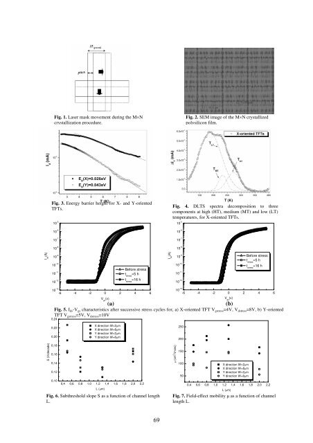
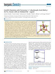
The Effect of Sub-boundaries on the Performance and Reliability of ovel SLS ELA Polysilicon TFTs M. A. Exarchos 1* , D. C. Moschou 2 , D. N. Kouvatsos 2 , G. J. Papaioannou 1 and A. T. Voutsas 3 1 Physics Department, National and Kapodistrian University of Athens, Athens 15784, Greece 2 Institute of Microelectronics, NCSR Demokritos, Agia Paraskevi 15310, Greece 3 LCD Process Technology Laboratory, Sharp Labs of America, 5700 NM Pacific Rim Blvd, Camas, WA 98607, USA *mexarcho@phys.uoa.gr Abstract Polysilicon TFTs fabricated in a film crystallized with a novel SLS ELA technique, yielding rectangular crystal domains much larger than the TFT channel dimensions, were investigated. The TFT channels were oriented both along the preferential direction and vertical to it, thus probing the sub-boundary effects of both directions. DLTS assessment was conducted on unstressed TFTs in order to probe the film’s defect nature. DC hot carrier stress was applied for both channel orientations, in order to elucidate the effect of the crystallization procedure and its resulting microstructure on the reliability of the devices. A dimensional optimization of the TFTs was found. 1. Introduction In this work we investigate the application of a novel SLS ELA polysilicon crystallization method [1-3], termed MN, for top gate TFTs oriented along both preferential and non-preferential directions. Through DLTS analysis the defect nature of the polysilicon film is probed. The relation between process characteristics and device reliability is elucidated through hotcarrier stress. An optimization of the TFT performance through variation of the channel length was attempted. 2. Experimental The TFTs studied were fabricated in polysilicon film formed by ELA crystallization of a:Si, using an SLS technique termed MN. In this procedure the mask (Fig. 1) consists of sets of slits orthogonal to each other. The grains grow first in the Y direction (via the "M" patterns) and, then, sub-boundaries within these grains are swept in the X direction (via the "N" patterns), which is therefore the preferential direction. This results in large domain sizes but of lower intragrain quality than other, multi-shot techniques. A SEM image of the polysilicon film can be seen in Fig. 2. Since the crystal domain is much larger than the TFT channel, no hard grain boundaries should be included in either direction. However, nanoscale subboundaries (evidenced by features like protrusions and hillocks) are present in both directions, known to affect the TFT performance [3]. DLTS assessment was conducted on unstressed TFTs, immediately after the device transition from OFF- to ON-state. Drain current spectra I d (T) were monitored and measured. Devices were stressed and characterized in both directions. The hot-carrier stress was applied for a maximum duration of 16 hours. 3. Results and Discussion DLTS measurements were conducted under the same bias conditions for unstressed TFTs. DLTS spectra magnitudes I d (T) are considerably higher for the devices having the channel aligned to X direction, than in Y direction. This is so because the respective energy barrier height E B of the grain boundaries is lower (Fig. 3) [4]. For X-oriented TFTs, E B (X)=0.026eV and for Y-oriented ones, E B (Y)=0.043eV. Further decomposed, the DLTS spectra for each oriented TFT disclosed three thermally activated contributions corresponding to three discrete traps (Fig. 4). Their activation energies were calculated in the range 0.39eV-0.53eV. The Arrhenius signatures closest to the detected defects are associated with hole traps originating from dislocations and rapid thermal annealing (RTA) defects. To probe the effect of the sub-boundaries on the reliability of our TFTs we applied hot-carrier stress, with V gstress =V dstress /2, on both channel orientations. A more severe degradation in the X orientation is revealed even for milder stress conditions (Fig. 5), due to the softer grain boundaries. Also, the parallel shift of the I DS -V GS characteristics in the Y direction is attributed to charges injected in the gate oxide, while in the X direction the curve distortion implies severe interface degradation. In Figs. 6, 7 we see that for channel lengths larger or smaller than 1.2m the performance seems to deteriorate. The increasing S with increasing L is attributed to more sub-boundaries included within the channel, while its increase with decreasing L is an electrical effect, ascribed to the increased channel charge in the subthreshold regime [5] due to the additional drain bias control of the channel region. These two mechanisms define the optimum TFT channel length for our crystallization process. 4. Conclusions SLS ELA polysilicon TFTs fabricated in films crystallized with a novel SLS ELA technique termed MN yielding large rectangular crystal domains were studied, with the TFT channels oriented along the preferential and the non-preferential direction. The DLTS analysis of the devices showed larger energy barrier height in the Y direction. Discrete traps deep in polysilicon energy gap were detected, originating from dislocations and rapid thermal annealing defects. TFT degradation seemed to be less pronounced in the Y direction, due to the harder sub-boundaries obstructing the stress current. The main degradation mechanism for the X direction was interface state generation, while for the Y direction the gate oxide charge injection. An optimum channel length was found, defined both by the sub-boundary characteristics and by electrical effects. References [1] A.T. Voutsas, IEEE Trans. Electron Dev. ED-50 (2003) 1494. [2] M.A. Crowder, M. Moriguchi, Y. Mitani and A.T. Voutsas, Thin Solid Films 427 (2003) 101. [3] A.T. Voutsas, A. Limanov and J.S. Im, J. Appl. Phys. 94 (2003) 7445. [4] Y.Morimoto et al, Journal of Electrochemical Society, 144, 7, pp 2495-2501, (1997) [5] A. G. Lewis et al, IEDM '89 Proc., pp. 349-352 (1999). 68
Fig. 1. Laser mask movement during the MN crystallization procedure. Fig. 2. SEM image of the MN crystallized polysilicon film. Fig. 3. Energy barrier height for X- and Y-oriented TFTs. Fig. 4. DLTS spectra decomposition to three components at high (HT), medium (MT) and low (LT) temperatures, for X-oriented TFTs. 10 -6 10 -6 10 -5 Before stress 10 -7 10 -7 10 -8 10 -8 I ds (A) 10 -5 Before stress 10 -9 10 -10 I ds (A) 10 -9 10 -10 t stress =5 h t stress =16 h 10 -11 10 -12 t stress =5 h t stress =16 h 10 -11 10 -12 10 -13 -6 -4 -2 0 2 4 6 V gs (v) (a) 10 -13 -6 -4 -2 0 2 4 6 Fig. 5. I ds -V gs characteristics after successive stress cycles for, a) X-oriented TFT V gstress =4V, V dstress =8V, b) Y-oriented TFT V gstress =5V, V dstress =10V 0,24 V gs (v) (b) 0,22 0,20 X direction W=2m X direction W=8m Y direction W=2m Y direction W=8m 250 200 S (V/decade) 0,18 0,16 0,14 0,12 0,10 0,4 0,6 0,8 1,0 1,2 1,4 1,6 1,8 2,0 2,2 L (m) Fig. 6. Subthreshold slope S as a function of channel length L. (cm 2 /V·sec) 150 100 50 X direction W=2m X direction W=8m Y direction W=2m Y direction W=8m 0,4 0,6 0,8 1,0 1,2 1,4 1,6 1,8 2,0 2,2 L (m) Fig. 7. Field-effect mobility as a function of channel length L. 69
- Page 1 and 2:
XXIII ΠΑΝΕΛΛΗΝΙΟ ΣΥΝΕ
- Page 3 and 4:
Κοιτώντας τα πρακτ
- Page 5 and 6:
ΕΠΙΤΡΟΠΕΣ Οργανωτι
- Page 7 and 8:
ΠΡΟΓΡΑΜΜΑ ΣΥΝΕΔΡΙΟ
- Page 9 and 10:
21. Οργανικά τρανζίσ
- Page 11 and 12:
15:30 15:45 16:00 16:15 16:30 16:45
- Page 13 and 14:
41. Modeling and quantitative phase
- Page 15 and 16:
Ανοιχτή Συνεδρία «
- Page 17 and 18:
«NανοΥλικά και Νανο
- Page 19 and 20:
New materials and MOS device concep
- Page 21 and 22:
Reliability Characteristics of Rare
- Page 23 and 24:
Ο λόγος των ταχυτήτ
- Page 25 and 26:
Thus the mean R In-In is expected t
- Page 27 and 28:
FIG 1. Schematic representation of
- Page 29 and 30:
με 0.80 eV στη διεπιφά
- Page 31 and 32:
Εντοπισµός Φορέων
- Page 33 and 34:
Παρασκευή και Xαρακ
- Page 35 and 36: Electrical Spin Injection from Fe i
- Page 37 and 38: Electrical Spin Injection of Spin-P
- Page 39 and 40: References [1] CH Lee, J. Meteer, V
- Page 41 and 42: Σχήμα 1: Φωτογραφία
- Page 43 and 44: SEM Image Layout Simulation Εικ
- Page 45 and 46: Μελέτη Ατελειών Σε
- Page 47 and 48: Facet-Stress-Driven Ordering in SiG
- Page 49 and 50: νανοκρυσταλλίτης (a
- Page 51 and 52: Σχήµα 1. Εικόνες περ
- Page 53 and 54: Σχήµα 1. Εικόνες περ
- Page 55 and 56: Οι δομές που αναπτύ
- Page 57 and 58: Raman Intensity (10 -50 cm 3 ) 1,2
- Page 59 and 60: Μελέτη της Επίδρασ
- Page 61 and 62: Annealing Induced Dissociation of N
- Page 63 and 64: `Εναπόθεση με Παλμι
- Page 65 and 66: Μελέτη της Χημείας
- Page 67 and 68: Ανάπτυξη Νέων Μεσο
- Page 69 and 70: Application of Thermal Quadrupoles
- Page 71 and 72: Στοχαστική προσομο
- Page 73 and 74: Νανοτραχύτητα κατά
- Page 75 and 76: Ευαισθησία και Δια
- Page 77 and 78: Optical Properties of CuIn 1-x Ga x
- Page 79 and 80: ανοπτημένο με λέιζ
- Page 81 and 82: Στο σχήμα 3 φαίνοντ
- Page 83 and 84: Id (mA) -0,3 -0,2 -0,1 Vg=0 Vg=-1 V
- Page 85: Strained-Si Si 1-x Ge x graded Si 1
- Page 89 and 90: forwarded to the back interface dur
- Page 91 and 92: Σχήμα 2: Εκθετική εξ
- Page 93 and 94: V th (V) G m,max /G m,max0 (%) I d
- Page 95 and 96: C/ C ox 1,0 0,8 0,6 0,4 0,2 0,0 -4
- Page 97 and 98: και Ta 2 O 5 , των οποίω
- Page 99 and 100: κατασκευή της. Η πα
- Page 101 and 102: ΔP (mW) 12 10 8 6 4 2 0 0 500 1000
- Page 103 and 104: υπολογίσουμε θεωρη
- Page 105 and 106: Σχήμα 2 Σύστημα ηλε
- Page 107 and 108: Μελέτη των Μηχανισ
- Page 109 and 110: Ανάπτυξη και Μελέτ
- Page 111 and 112: Structure and Magnetic Properties o
- Page 113 and 114: Δομή και Μαγνητικέ
- Page 115 and 116: Μετρήσεις Ειδικής
- Page 117 and 118: Further, almost all of the observed
- Page 119 and 120: g-factor 2.019 2.016 2.013 2.010 2.
- Page 121 and 122: ρυθμό 4 C.min -1 , έπειτ
- Page 123 and 124: ΜΕΛΕΤΗ ΤΟΥ ΦΑΙΝΟΜΕ
- Page 125 and 126: Νέοι Εξαφερίτες Ba µ
- Page 127 and 128: Crystal Structure of a new Supramol
- Page 129 and 130: Magnetic Phase Transition in Synthe
- Page 131 and 132: Συσχέτιση πλαστική
- Page 133 and 134: Μετασχηματισμοί φά
- Page 135 and 136: Μελέτη της Επίδρασ
- Page 137 and 138:
Resonant Spin Transfer Torque in Do
- Page 139 and 140:
3 η Προφορική Συνεδ
- Page 141 and 142:
technology, and e-beam lithography.
- Page 143 and 144:
ecause it reduces the calculation o
- Page 145 and 146:
Υπολογισμός Υψηλής
- Page 147 and 148:
The thermodynamic average is obtain
- Page 149 and 150:
ΑΠΟΤΕΛΕΣΜΑΤΑ Στην
- Page 151 and 152:
προερχόµενη είτε α
- Page 153 and 154:
Combining Magnetism and Ferroelectr
- Page 155 and 156:
υµένια LCMO/STO (100) πολ
- Page 157 and 158:
Our scheme is illustrated in Fig. 1
- Page 159 and 160:
[6] . Η μελέτη του υλι
- Page 161 and 162:
τα πειραµατικά µας
- Page 163 and 164:
συµπύκνωµα. Αυτό επ
- Page 165 and 166:
και αναδεικνύει τρ
- Page 167 and 168:
P P P P P power P copolymers P and
- Page 169 and 170:
Αυτο-οργάνωση και Μ
- Page 171 and 172:
Viscoelastic Response of Micelles w
- Page 173 and 174:
Διηλεκτρική απόκρι
- Page 175 and 176:
Light - induced Reversible Hydrophi
- Page 177 and 178:
Οι παραπάνω τρεις κ
- Page 179 and 180:
AP-PH (a.u.) 0.4 0.3 0.2 0.1 0.0 0
- Page 181 and 182:
Synthesis of Polymer Brushes onto I
- Page 183 and 184:
Conformational Properties of Dendri
- Page 185 and 186:
Structure and Dynamics of Branched
- Page 187 and 188:
∆οµή και ∆υναµική
- Page 189 and 190:
Επίδραση της Τοπολ
- Page 191 and 192:
(α) (β) Σχήμα 2: (α) Απε
- Page 193 and 194:
Figure 3. Generation 4 PAMAM-H 2 O
- Page 195 and 196:
Από όλα τα παραπάνω
- Page 197 and 198:
Το PHEGMA είναι άμορφο
- Page 199 and 200:
PS HAuCl 4 P2VP Ion loading PSP2VP
- Page 201 and 202:
The nonlinear optical response of A
- Page 203 and 204:
νανοσωµατίδια. Όπω
- Page 205 and 206:
Bioactive Glass/Nanodiamonds system
- Page 207 and 208:
Energy Loss Rates of Hot Electrons
- Page 209 and 210:
Σύνθεση και Χαρακτ
- Page 211 and 212:
μπορεί να ερμηνευτ
- Page 213 and 214:
Nανοσυνθέτα Εποξει
- Page 215 and 216:
[1] S. Iijima, Nature 354, 56 (1991
- Page 217 and 218:
Figure 3: GCMC calculations for und
- Page 219 and 220:
μερών, εμφανίζοντα
- Page 221 and 222:
1.0 Reflectance 1.1 1.0 0.9 0.8 0.7
- Page 223 and 224:
στο συντελεστή διέ
- Page 225 and 226:
¿ÔÖØÑÒØÓÐØÖÐÒÒÖÒ¸
- Page 227 and 228:
Συναπόθεση Cr - Ni σε
- Page 229 and 230:
Investigation of the Structural, Mo
- Page 231 and 232:
Modification of Perlite Cementitiou
- Page 233 and 234:
Templated Sol-Gel Synthesis Of TiO
- Page 235 and 236:
Παρασκευή Υμενίων
- Page 237 and 238:
Preparation of YSZ Solid Electrolyt
- Page 239 and 240:
Σύνθεση, Ανισοτροπ
- Page 241 and 242:
Μελέτη ανθρώπινων
- Page 243 and 244:
Local Coordination of Zn and Fe in
- Page 245 and 246:
Επίδραση της Προσθ
- Page 247 and 248:
Αλκαλική Σύνθεση κ
- Page 249 and 250:
Μηχανικές Iδιότητε
- Page 251 and 252:
The Influence of Thermal Aging on t
- Page 253 and 254:
Modeling and quantitative phase ana
- Page 255 and 256:
Συμβολή στη Συντήρ
- Page 257 and 258:
Κρυσταλλική Συµπερ
- Page 259 and 260:
Σύνθεση Στερεών ∆ι
- Page 261 and 262:
Fabrication and Characterization of
- Page 263 and 264:
∆ιερεύνηση δυνατό
- Page 265 and 266:
Συγκριτική αξιολόγ
- Page 267 and 268:
6 η Προφορική Συνεδ
- Page 269 and 270:
Ηλεκτρομαγνητική Α
- Page 271 and 272:
Φασματοσκοπική Μελ
- Page 273 and 274:
Thermal and Electrical Properties o
- Page 275 and 276:
Structure, Mechanical, and Optoelec
- Page 277 and 278:
Designing Nanoporous Materials for
- Page 279 and 280:
This program was developed to serve
- Page 281 and 282:
Νέα Αυτό-οργανούμε
- Page 283 and 284:
A Physical Model to Interpret the E
- Page 285 and 286:
FIR study of Ag x (As 33 S 33 Se 33
- Page 287 and 288:
Mελέτη Μεικτών Γυαλ
- Page 289 and 290:
The Structural Role of Fe and Zn in
- Page 291 and 292:
ΕΥΡΕΤΗΡΙΟ ΣΥΓΓΡΑΦΕ
- Page 293 and 294:
Κομπίτσας Μ…………
- Page 295 and 296:
ΕΥΡΕΤΗΡΙΟ ΣΥΓΓΡΑΦΕ
- Page 297:
W Watson I.M………………4 Weg