- Page 1 and 2:
© Siemens AG, 2009 Instrumentos pa
- Page 3 and 4:
Instrumentos para medida de caudal
- Page 5 and 6:
Instrumentos para medida de caudal
- Page 7 and 8:
Instrumentos para medida de caudal
- Page 9 and 10:
■ Sinopsis Criterios para la sele
- Page 11 and 12:
■ Sinopsis Serie SITRANS F M Los
- Page 13 and 14:
Para algunos productos puede haber
- Page 15 and 16:
Para algunos productos puede haber
- Page 17 and 18:
■ Ejemplos para la aplicación en
- Page 19 and 20:
1. Ensayo del transmisor El ensayo
- Page 21 and 22:
■ Datos técnicos PROFIBUS PA/DP
- Page 23 and 24:
Sistema métrico imperial Tabla de
- Page 25 and 26:
Medida de líquidos corrosivos y co
- Page 27 and 28:
Cable al sensor y conductividad del
- Page 29 and 30:
■ Datos técnicos Modo de operaci
- Page 31 and 32:
Modo de operación La unidad de lim
- Page 33 and 34:
Descripción Referencia MAG 6000 co
- Page 35 and 36:
■ Croquis acotados Transmisor IP6
- Page 37 and 38:
Transmisor, montaje en panel fronta
- Page 39 and 40:
■ Diagramas de circuitos Puesta a
- Page 41 and 42:
Error de medida máx. MAG 6000 I/MA
- Page 43 and 44:
■ Croquis acotados 220 (8.66) 20
- Page 45 and 46:
© Siemens AG, 2009 Instrumentos pa
- Page 47 and 48:
000000000000 000000000000 Datos par
- Page 49 and 50:
■ Croquis acotados Sensor MAG 110
- Page 51 and 52:
■ Sinopsis El sensor electromagn
- Page 53 and 54:
Datos para selección y pedidos Ref
- Page 55 and 56:
Accesorios Piezas de conexión de r
- Page 57 and 58:
Sensor MAG 1100 F, compacto/separad
- Page 59 and 60: ■ Datos técnicos Instrumentos pa
- Page 61 and 62: ■ Croquis acotados - No disponibl
- Page 63 and 64: © Siemens AG, 2009 Instrumentos pa
- Page 65 and 66: ■ Datos técnicos Instrumentos pa
- Page 67 and 68: Material de la tubería de medició
- Page 69 and 70: Datos para selección y pedidos Cla
- Page 71 and 72: Datos para selección y pedidos Ref
- Page 73 and 74: Datos para selección y pedidos Ani
- Page 75 and 76: © Siemens AG, 2009 Datos para sele
- Page 77 and 78: © Siemens AG, 2009 Instrumentos pa
- Page 79 and 80: ■ Sinopsis Transmisores SITRANS F
- Page 81 and 82: Forma constructiva Peso del transmi
- Page 83 and 84: ■ Croquis acotados Instrumentos p
- Page 85 and 86: Discos de protección para los reve
- Page 87 and 88: Datos para selección y pedidos SIT
- Page 89 and 90: Datos para selección y pedidos SIT
- Page 91 and 92: Datos para selección y pedidos Ref
- Page 93 and 94: Sensor 911/E SITRANS F M, versión
- Page 95 and 96: © Siemens AG, 2009 Instrumentos pa
- Page 97 and 98: Salida digital MAG 8000 • 2 salid
- Page 99 and 100: Incertidumbre del contador de agua
- Page 101 and 102: Configuración de las salidas MAG 8
- Page 103 and 104: Datos para selección y pedidos Ref
- Page 105 and 106: Datos para selección y pedidos SIT
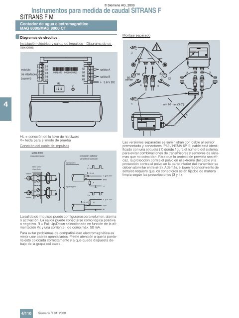
- Page 107 and 108: El MAG 8000 presenta electrodos de
- Page 109: Versión separada Dimensiones en mm
- Page 113 and 114: Infórmese con nuestro selector de
- Page 115 and 116: ■ Funciones El principio de la me
- Page 117 and 118: 1) Requiere calibración de densida
- Page 119 and 120: ■ Sinopsis El MASS 6000 ha sido d
- Page 121 and 122: Datos para selección y pedidos Ref
- Page 123 and 124: ■ Sinopsis El MASS 6000 ha sido d
- Page 125 and 126: Datos para selección y pedidos Ref
- Page 127 and 128: ■ Croquis acotados Transmisor, m
- Page 129 and 130: ■ Diagramas de circuitos Conexió
- Page 131 and 132: © Siemens AG, 2009 Instrumentos pa
- Page 133 and 134: ■ Croquis acotados Transmisor MAS
- Page 135 and 136: ■ Datos técnicos Medición de Ca
- Page 137 and 138: ■ Diagramas de circuitos
- Page 139 and 140: Instrumentos para medida de caudal
- Page 141 and 142: ■ Croquis acotados MASS 2100 DI 1
- Page 143 and 144: Instrumentos para medida de caudal
- Page 145 and 146: ■ Croquis acotados
- Page 147 and 148: ■ Funciones El principio de medic
- Page 149 and 150: Caída de presión Δp [bar] 10 1,0
- Page 151 and 152: Datos para selección y pedidos Ref
- Page 153 and 154: ■ Croquis acotados Sensor de medi
- Page 155 and 156: Sensor MASS 2100 con camisa calenta
- Page 157 and 158: ■ Funciones El principio de medic
- Page 159 and 160: Datos para selección y pedidos Ref
- Page 161 and 162:
■ Croquis acotados Construcción
- Page 163 and 164:
Conexiones al proceso • Bridas DI
- Page 165 and 166:
Instrumentos para medida de caudal
- Page 167 and 168:
Construcción separada, Tri-Clamp D
- Page 169 and 170:
Para algunos productos puede haber
- Page 171 and 172:
Para algunos productos puede haber
- Page 173 and 174:
■ Datos técnicos MGD (US) 500 20
- Page 175 and 176:
Se recomienda instalar los converti
- Page 177 and 178:
• Sentido de flujo • Función d
- Page 179 and 180:
■ Croquis acotados SITRANS F
- Page 181 and 182:
■ Sinopsis La combinación del se
- Page 183 and 184:
Datos para selección y pedidos Ref
- Page 185 and 186:
■ Croquis acotados Sensores SONO
- Page 187 and 188:
Datos para selección y pedidos Ref
- Page 189 and 190:
Carcasa de la caja de bornes 1) ATE
- Page 191 and 192:
Pasacables SONO 3200 Tipo/Descripci
- Page 193 and 194:
B D ... D 10 300 Du L ... L 10 300
- Page 195 and 196:
Materiales de la tubería existente
- Page 197 and 198:
Datos para selección y pedidos Ref
- Page 199 and 200:
Instrumentos para medida de caudal
- Page 201 and 202:
Instrumentos para medida de caudal
- Page 203 and 204:
© Siemens AG, 2009 Instrumentos pa
- Page 205 and 206:
FUS380 Ajuste valor de caudal Preaj
- Page 207 and 208:
Datos para selección y pedidos Cla
- Page 209 and 210:
© Siemens AG, 2009 Instrumentos pa
- Page 211 and 212:
Frecuencia de medida Servicio por b
- Page 213 and 214:
© Siemens AG, 2009 Instrumentos pa
- Page 215 and 216:
■ Croquis acotados Instrumentos
- Page 217 and 218:
■ Diagramas de circuitos Conexió
- Page 219 and 220:
Indicadores e impulsos de salida Un
- Page 221 and 222:
■ Datos para selección y pedidos
- Page 223 and 224:
■ Diagramas de circuitos Conexió
- Page 225 and 226:
PVC macizo PIP 80 Soporte del conve
- Page 227 and 228:
Datos para selección y pedidos Ref
- Page 229 and 230:
Instrumentos para medida de caudal
- Page 231 and 232:
Los caudalímetros ultrasónicos SI
- Page 233 and 234:
Información del sistema y sinopsis
- Page 235 and 236:
■ Funciones Funcionamiento El sis
- Page 237 and 238:
Cálculo de volumen estándar: El c
- Page 239 and 240:
Instrumentos para medida de caudal
- Page 241 and 242:
FUP1010: Caja resistente a la intem
- Page 243 and 244:
FUS1020: Caja para montaje en pared
- Page 245 and 246:
■ Datos técnicos SITRANS FUS1010
- Page 247 and 248:
SITRANS FUS1010, caja protegida con
- Page 249 and 250:
Datos para selección y pedidos SIT
- Page 251 and 252:
■ Sinopsis El calculador ultrasó
- Page 253 and 254:
Datos para selección y pedidos Ref
- Page 255 and 256:
■ Ejemplo de pedido Ejemplo de ap
- Page 257 and 258:
■ Sinopsis El SITRANS FUE1010 es
- Page 259 and 260:
Datos para selección y pedidos Ref
- Page 261 and 262:
Datos para selección y pedidos Cla
- Page 263 and 264:
■ Sinopsis El juego de medición
- Page 265 and 266:
■ Datos técnicos SITRANS FUH1010
- Page 267 and 268:
Datos para selección y pedidos Ref
- Page 269 and 270:
■ Ejemplo de pedido Ejemplo de ap
- Page 271 and 272:
■ Datos técnicos SITRANS FUG1010
- Page 273 and 274:
Datos para selección y pedidos Ref
- Page 275 and 276:
■ Ejemplo de pedido Ejemplo de ap
- Page 277 and 278:
Datos para selección y pedidos Ref
- Page 279 and 280:
© Siemens AG, 2009 Instrumentos pa
- Page 281 and 282:
Datos para selección y pedidos Ref
- Page 283 and 284:
Datos para selección y pedidos Pie
- Page 285 and 286:
Tabla de selección de cables para
- Page 287 and 288:
Instrumentos para medida de caudal
- Page 289 and 290:
■ Sinopsis Los caudalímetros SIT
- Page 291 and 292:
Datos para selección y pedidos Ref
- Page 293 and 294:
Datos para selección y pedidos Ref
- Page 295 and 296:
■ Croquis acotados Versión de br
- Page 297 and 298:
© Siemens AG, 2009 Instrumentos pa
- Page 299 and 300:
Diseño tipo sandwich EN Diámetro
- Page 301 and 302:
Rango de medida vapor de agua satur
- Page 303 and 304:
■ Sinopsis Rotámetro SITRANS FVA
- Page 305 and 306:
Salida analógica con transmisor ma
- Page 307 and 308:
■ Croquis acotados SITRANS
- Page 309 and 310:
Cono de medida Rango de medida para
- Page 311 and 312:
■ Órganos deprimógenos según D
- Page 313 and 314:
30 G1/2 18,5 11 h11 8,7 21,3 3 Cone
- Page 315 and 316:
■ Características La placa de or
- Page 317 and 318:
■ Sinopsis La Directiva de aparat
- Page 319 and 320:
s Idioma del informe de cálculo Cl
- Page 321 and 322:
■ Gama de aplicación Adecuado pa
- Page 323 and 324:
Diámetro nominal según ASME © Si
- Page 325 and 326:
Datos para selección y pedidos Ref
- Page 327 and 328:
■ Gama de aplicación Adecuado pa
- Page 329 and 330:
Datos para selección y pedidos Ref
- Page 331 and 332:
Otras versiones Clave1) Datos para
- Page 333 and 334:
■ Croquis acotados Diámetro nomi
- Page 335 and 336:
Otras versiones Clave1) Datos para
- Page 337 and 338:
■ Croquis acotados Diámetro nomi
- Page 339 and 340:
Otras versiones Clave1) Datos para
- Page 341 and 342:
Instrumentos para medida de caudal
- Page 343 and 344:
■ Beneficios • alta precisión
- Page 345 and 346:
■ Configuraciones de los contador
- Page 347 and 348:
Volumen mínimo dispensable y volum
- Page 349 and 350:
Instrumentos para medida de caudal
- Page 351 and 352:
Sustancias Instrumentos para medida
- Page 353 and 354:
Precisión Los contadores de émbol
- Page 355 and 356:
Materiales del émbolo 1) para 120
- Page 357 and 358:
Ejemplo de pedido 1 Se desea: Un co
- Page 359 and 360:
■ Informaciones de importancia pa
- Page 361 and 362:
Instrumentos para medida de caudal
- Page 363 and 364:
■ Informaciones de importancia pa
- Page 365 and 366:
■ Informaciones de importancia pa
- Page 367 and 368:
Instrumentos para medida de caudal
- Page 369 and 370:
■ Informaciones de importancia pa
- Page 371 and 372:
■ Croquis acotados Dimensiones de
- Page 373 and 374:
Contador de émbolo rotativo DN 15
- Page 375 and 376:
Instrumentos para medida de caudal
- Page 377 and 378:
© Siemens AG, 2009 Contador de ém
- Page 379 and 380:
Instrumentos para medida de caudal
- Page 381 and 382:
© Siemens AG, 2009 Instrumentos pa
- Page 383 and 384:
© Siemens AG, 2009 Instrumentos pa
- Page 385 and 386:
Dosificador automático DN 25 (1")
- Page 387 and 388:
■ Sinopsis Indicadores y preselec
- Page 389 and 390:
Instrumentos para medida de caudal
- Page 391 and 392:
Instrumentos para medida de caudal
- Page 393 and 394:
Construcción mecánica Material Ca
- Page 395 and 396:
■ Sinopsis Emisor de impulsos con
- Page 397 and 398:
■ Sinopsis Reductor El reductor p
- Page 399 and 400:
■ Sinopsis Para prolongar el vari