Intel® 865G/865GV Chipset Datasheet - download.intel.nl - Intel
Intel® 865G/865GV Chipset Datasheet - download.intel.nl - Intel
Intel® 865G/865GV Chipset Datasheet - download.intel.nl - Intel

Create successful ePaper yourself
Turn your PDF publications into a flip-book with our unique Google optimized e-Paper software.
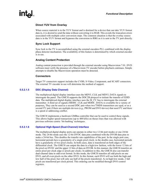
Functional DescriptionDirect YUV from OverlayWhen source material is in the YUV format and is destined for a device that can take YUV formatdata in, it is desired to send the data without converting it to RGB. This avoids the truncation errorsassociated with multiple color conversion steps. The common situation is that the overlay sourcedata is in the YUV format and bypasses the conversion to RBG as it is sent to the TV port directly.Sync Lock SupportSync lock to the TV is accomplished using the external encoders PLL combined with the displayphase detector mechanism. The availability of this feature is determined by which external encoderis in use.Analog Content ProtectionAnalog content protection is provided through the external encoder using Macrovision 7.01. DVDsoftware must verify the presence of a Macrovision TV encoder before playback continues. Simpleattempts to disable the Macrovision operation must be detected.ConnectorsTarget TV connectors support includes the CVBS, S-Video, Component, and SCART connectors.The external TV encoder in use will determine the method of support.5.5.2.1.5 DDC (Display Data Channel)The multiplexed digital display interface uses the MDVI_CLK and MDVI_DATA signals tointerrogate the panel. The GMCH supports the DDC2B protocol to initiate the transfer of EDIDdata. The multiplexed digital display interface uses the M_I 2 C bus to interrogate the externaltransmitter. A third set of signals (MDDC_CLK and MDDC_DATA) is available for a variety ofpurposes. They can be used as a second DDC pair when two TMDS transmitters are used, or as asecond I 2 C pair if there are multiple devices (e.g., PROM and DVO device) that need I 2 C and thereis a speed or addressing conflict.The GMCH implements a hardware GMBus controller that can be used to control these signals.This allows higher speed transactions (up to 400 kHz) on theses lines than was allowed withprevious software centric ‘bit-bashing’ techniques.5.5.2.1.6 Optional High-Speed (Dual-Channel) InterfaceThe multiplexed digital display ports can operate in either two 12-bit port modes or one 24-bitmode. The 24-bit mode uses the 12-bit DVOC data pins combined with the DVOB data pins tomake a 24-bit bus. This doubles the transfer rate capabilities of the port. In the single port case,horizontal periods have a granularity of a single pixel clock; in the double case, horizontal periodshave a granularity of two pixel clocks. In both cases, data is transferred on both edges of thedifferential clock. The GMCH can output the data in a high-low fashion, with the lower 12 bits ofthe pixel on DVOC and the upper 12 bits of data on DVOB. In this manner, the GMCH transfers anentire pixel per clock edge (2 pixels per clock). In addition to this, the GMCH also can transferdual-channel data in odd-even format. In this mode, the GMCH transfers all odd pixels on oneDVO, and all even pixels on the other DVO. In this format, each DVO will see both the high andlow half of the pixel, but will o<strong>nl</strong>y see half of the pixels transferred. As in high-low mode, 2 fullpixels are transferred per clock period. This ordering can be modified through DVO controlregisters.<strong>Intel</strong> ® 82<strong>865G</strong>/82<strong>865G</strong>V GMCH <strong>Datasheet</strong> 179