

sepam 20 user manual - Schneider Electric
sepam 20 user manual - Schneider Electric
sepam 20 user manual - Schneider Electric

Create successful ePaper yourself
Turn your PDF publications into a flip-book with our unique Google optimized e-Paper software.
6<br />
Installation Voltage transformers<br />
6/28<br />
DANGER<br />
HAZARD OF ELECTRIC SHOCK, ELECTRIC<br />
ARC OR BURNS<br />
b Only qualified personnel should install this<br />
equipment. Such work should be performed only<br />
after reading this entire set of instructions and<br />
checking the technical characteristics of the<br />
device.<br />
b NEVER work alone.<br />
b Turn off all power supplying this equipment<br />
before working on or inside it. Consider all<br />
sources of power, including the possibility of<br />
backfeeding.<br />
b Always use a properly rated voltage sensing<br />
device to confirm that all power is off.<br />
b Start by connecting the device to the<br />
protective earth and to the functional earth.<br />
b Screw tight all terminals, even those not in<br />
use.<br />
Failure to follow these instructions will result<br />
in death or serious injury.<br />
DE50565<br />
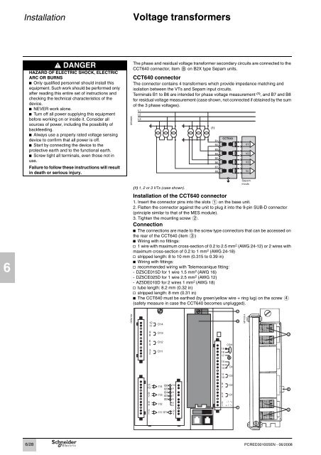
The phase and residual voltage transformer secondary circuits are connected to the<br />
CCT640 connector, item B on B2X type Sepam units.<br />
CCT640 connector<br />
The connector contains 4 transformers which provide impedance matching and<br />
isolation between the VTs and Sepam input circuits.<br />
Terminals B1 to B6 are intended for phase voltage measurement (1) , and B7 and B8<br />
for residual voltage measurement (case shown, not connected if obtained by the sum<br />
of the 3 phase voltages).<br />
(1) 1, 2 or 3 VTs (case shown).<br />
Installation of the CCT640 connector<br />
1. Insert the connector pins into the slots on the base unit.<br />
2. Flatten the connector against the unit to plug it into the 9-pin SUB-D connector<br />
(principle similar to that of the MES module).<br />
3. Tighten the mounting screw .<br />
Connection<br />
b The connections are made to the screw type connectors that can be accessed on<br />
the rear of the CCT640 (item )<br />
b Wiring with no fittings:<br />
v 1 wire with maximum cross-section of 0.2 to 2.5 mm2 (AWG 24-12) or 2 wires with<br />
maximum cross-section of 0.2 to 1 mm2 (AWG 24-18)<br />
v stripped length: 8 to 10 mm (0.315 to 0.39 in)<br />
b Wiring with fittings:<br />
v recommended wiring with Telemecanique fitting:<br />
- DZ5CE015D for 1 wire 1.5 mm2 (AWG 16)<br />
- DZ5CE025D for 1 wire 2.5 mm2 (AWG 12)<br />
- AZ5DE010D for 2 wires 1 mm2 1<br />
2<br />
3<br />
(AWG 18)<br />
v tube length: 8.2 mm (0.32 in)<br />
v stripped length: 8 mm (0.31 in)<br />
b The CCT640 must be earthed (by green/yellow wire + ring lug) on the screw 4<br />
(safety measure in case the CCT640 becomes unplugged).<br />
DE52152<br />
MT10514<br />
PCRED301005EN - 06/<strong>20</strong>08<br />
3<br />
4<br />
3


