

sepam 20 user manual - Schneider Electric
sepam 20 user manual - Schneider Electric
sepam 20 user manual - Schneider Electric

You also want an ePaper? Increase the reach of your titles
YUMPU automatically turns print PDFs into web optimized ePapers that Google loves.
5<br />
PE50587<br />
Modbus communication Commissioning and diagnosis<br />
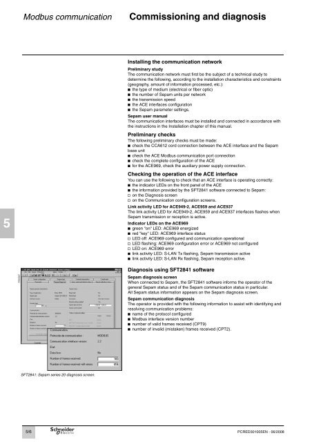
SFT2841: Sepam series <strong>20</strong> diagnosis screen.<br />
5/6<br />
Installing the communication network<br />
Preliminary study<br />
The communication network must first be the subject of a technical study to<br />
determine the following, according to the installation characteristics and constraints<br />
(geography, amount of information processed, etc.):<br />
b the type of medium (electrical or fiber optic)<br />
b the number of Sepam units per network<br />
b the transmission speed<br />
b the ACE interfaces configuration<br />
b the Sepam parameter settings.<br />
Sepam <strong>user</strong> <strong>manual</strong><br />
The communication interfaces must be installed and connected in accordance with<br />
the instructions in the Installation chapter of this <strong>manual</strong>.<br />
Preliminary checks<br />
The following preliminary checks must be made:<br />
b check the CCA612 cord connection between the ACE interface and the Sepam<br />
base unit<br />
b check the ACE Modbus communication port connection<br />
b check the complete configuration of the ACE<br />
b for the ACE969, check the auxiliary power supply connection.<br />
Checking the operation of the ACE interface<br />
You can use the following to check that an ACE interface is operating correctly:<br />
b the indicator LEDs on the front panel of the ACE<br />
b the information provided by the SFT2841 software connected to Sepam:<br />
v on the Diagnosis screen<br />
v on the Communication configuration screens.<br />
Link activity LED for ACE949-2, ACE959 and ACE937<br />
The link activity LED for ACE949-2, ACE959 and ACE937 interfaces flashes when<br />
Sepam transmission or reception is active.<br />
Indicator LEDs on the ACE969<br />
b green "on" LED: ACE969 energized<br />
b red "key" LED: ACE969 interface status<br />
v LED off: ACE969 configured and communication operational<br />
v LED flashing: ACE969 configuration error or ACE969 not configured<br />
v LED on: ACE969 error<br />
b link activity LED: S-LAN Tx flashing, Sepam transmission active<br />
b link activity LED: S-LAN Rx flashing, Sepam reception active.<br />
Diagnosis using SFT2841 software<br />
Sepam diagnosis screen<br />
When connected to Sepam, the SFT2841 software informs the operator of the<br />
general Sepam status and of the Sepam communication status in particular.<br />
All Sepam status information appears on the Sepam diagnosis screen.<br />
Sepam communication diagnosis<br />
The operator is provided with the following information to assist with identifying and<br />
resolving communication problems:<br />
b name of the protocol configured<br />
b Modbus interface version number<br />
b number of valid frames received (CPT9)<br />
b number of invalid (mistaken) frames received (CPT2).<br />
PCRED301005EN - 06/<strong>20</strong>08


