

sepam 20 user manual - Schneider Electric
sepam 20 user manual - Schneider Electric
sepam 20 user manual - Schneider Electric

Create successful ePaper yourself
Turn your PDF publications into a flip-book with our unique Google optimized e-Paper software.
DE50247<br />
DE50248<br />
Protection functions Earth fault<br />
ANSI code 50N/51N or 50G/51G<br />
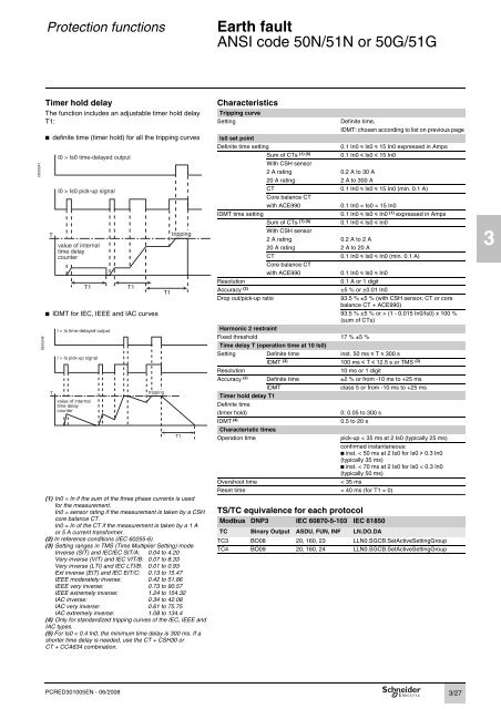
Timer hold delay Characteristics<br />
The function includes an adjustable timer hold delay<br />
T1:<br />
b definite time (timer hold) for all the tripping curves<br />
PCRED301005EN - 06/<strong>20</strong>08<br />
Tripping curve<br />
Setting Definite time,<br />
IDMT: chosen according to list on previous page<br />
Is0 set point<br />
Definite time setting 0.1 In0 y Is0 y 15 In0 expressed in Amps<br />
Sum of CTs (1) (5) 0.1 In0 y Is0 y 15 In0<br />
With CSH sensor<br />
2 A rating 0.2 A to 30 A<br />
<strong>20</strong> A rating 2 A to 300 A<br />
CT 0.1 In0 y Is0 y 15 In0 (min. 0.1 A)<br />
Core balance CT<br />
with ACE990 0.1 In0 < Is0 < 15 In0<br />
IDMT time setting 0.1 In0 y Is0 y In0 (1) expressed in Amps<br />
Sum of CTs (1) (5) 0.1 In0 y Is0 y In0<br />
With CSH sensor<br />
2 A rating 0.2 A to 2 A<br />
<strong>20</strong> A rating 2 A to <strong>20</strong> A<br />
CT 0.1 In0 y Is0 y In0 (min. 0.1 A)<br />
Core balance CT<br />
with ACE990 0.1 In0 y Is0 y In0<br />
Resolution 0.1 A or 1 digit<br />
Accuracy (2) ±5 % or ±0.01 In0<br />
Drop out/pick-up ratio 93.5 % ±5 % (with CSH sensor, CT or core<br />
balance CT + ACE990)<br />
b IDMT for IEC, IEEE and IAC curves 93.5 % ±5 % or > (1 - 0.015 In0/Is0) x 100 %<br />
(sum of CTs)<br />
T<br />
I > Is time-delayed output<br />
I > Is pick-up signal<br />
value of internal<br />
time delay<br />
counter<br />
tripping<br />
(1) In0 = In if the sum of the three phase currents is used<br />
for the measurement.<br />
In0 = sensor rating if the measurement is taken by a CSH<br />
core balance CT.<br />
In0 = In of the CT if the measurement is taken by a 1 A<br />
or 5 A current transformer.<br />
(2) In reference conditions (IEC 60255-6).<br />
(3) Setting ranges in TMS (Time Multiplier Setting) mode<br />
Inverse (SIT) and IECIEC SIT/A: 0.04 to 4.<strong>20</strong><br />
Very inverse (VIT) and IEC VIT/B: 0.07 to 8.33<br />
Very inverse (LTI) and IEC LTI/B: 0.01 to 0.93<br />
Ext inverse (EIT) and IEC EIT/C: 0.13 to 15.47<br />
IEEE moderately inverse: 0.42 to 51.86<br />
IEEE very inverse: 0.73 to 90.57<br />
IEEE extremely inverse: 1.24 to 154.32<br />
IAC inverse: 0.34 to 42.08<br />
IAC very inverse: 0.61 to 75.75<br />
IAC extremely inverse: 1.08 to 134.4<br />
(4) Only for standardized tripping curves of the IEC, IEEE and<br />
IAC types.<br />
(5) For Is0 < 0.4 In0, the minimum time delay is 300 ms. If a<br />
shorter time delay is needed, use the CT + CSH30 or<br />
CT + CCA634 combination.<br />
T1<br />
Harmonic 2 restraint<br />
Fixed threshold 17 % ±5 %<br />
Time delay T (operation time at 10 Is0)<br />
Setting Definite time inst. 50 ms y T y 300 s<br />
IDMT (3) 100 ms y T y 12.5 s or TMS (3)<br />
Resolution 10 ms or 1 digit<br />
Accuracy (2) Definite time ±2 % or from -10 ms to +25 ms<br />
IDMT class 5 or from -10 ms to +25 ms<br />
Timer hold delay T1<br />
Definite time<br />
(timer hold) 0; 0.05 to 300 s<br />
IDMT (4) 0.5 to <strong>20</strong> s<br />
Characteristic times<br />
Operation time pick-up < 35 ms at 2 Is0 (typically 25 ms)<br />
confirmed instantaneous:<br />
b inst. < 50 ms at 2 Is0 for Is0 u 0.3 In0<br />
(typically 35 ms)<br />
b inst. < 70 ms at 2 Is0 for Is0 < 0.3 In0<br />
(typically 50 ms)<br />
Overshoot time < 35 ms<br />
Reset time < 40 ms (for T1 = 0)<br />
TS/TC equivalence for each protocol<br />
Modbus DNP3 IEC 60870-5-103 IEC 61850<br />
TC Binary Output ASDU, FUN, INF LN.DO.DA<br />
TC3 BO08 <strong>20</strong>, 160, 23 LLN0.SGCB.SetActiveSettingGroup<br />
TC4 BO09 <strong>20</strong>, 160, 24 LLN0.SGCB.SetActiveSettingGroup<br />
3/27<br />
3


