

sepam 20 user manual - Schneider Electric
sepam 20 user manual - Schneider Electric
sepam 20 user manual - Schneider Electric

You also want an ePaper? Increase the reach of your titles
YUMPU automatically turns print PDFs into web optimized ePapers that Google loves.
Protection functions Thermal overload<br />
ANSI code 49RMS<br />
Description<br />
This function is used to protect equipment (motors,<br />
transformers, generators, lines, capacitors) against<br />
overloads, based on measurement of the current<br />
consumed.<br />
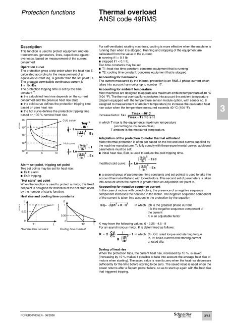
Operation curve<br />
The protection gives a trip order when the heat rise E,<br />
calculated according to the measurement of an<br />
equivalent current Ieq, is greater than the set point Es.<br />
The greatest permissible continuous current is<br />
MT10858<br />
The protection tripping time is set by the time<br />
constant T.<br />
b the calculated heat rise depends on the current<br />
consumed and the previous heat rise state<br />
b the cold curve defines the protection tripping time<br />
based on zero heat rise<br />
b the hot curve defines the protection tripping time<br />
based on 100 % nominal heat rise.<br />
Alarm set point, tripping set point<br />
Two set points may be set for heat rise:<br />
b Es1: alarm<br />
b Es2: tripping.<br />
"Hot state" set point<br />
When the function is used to protect a motor, this fixed<br />
set point is designed for detection of the hot state used<br />
by the number of starts function.<br />
Heat rise and cooling time constants<br />
MT10419<br />
I = Ib Es<br />
10 1<br />
10 0<br />
10 -1<br />
10 -2<br />
10 -3<br />
E<br />
1<br />
0,63<br />
0<br />
0 5 10<br />
T1<br />
Heat rise time constant. Cooling time constant.<br />
PCRED301005EN - 06/<strong>20</strong>08<br />
t<br />
MT104<strong>20</strong><br />
Cold curve<br />
⎛leq -------- ⎞<br />
t ⎝ lb ⎠<br />
-- L n<br />
T<br />
2<br />
⎛leq -------- ⎞<br />
⎝ lb ⎠<br />
2<br />
= -------------------------------<br />
– Es<br />
Hot curve<br />
⎛leq -------- ⎞<br />
t ⎝ lb ⎠<br />
-- L n<br />
T<br />
2<br />
– 1<br />
⎛leq -------- ⎞<br />
⎝ lb ⎠<br />
2<br />
= -------------------------------<br />
– Es<br />
E<br />
1<br />
0,36<br />
0<br />
T2<br />
t<br />
For self-ventilated rotating machines, cooling is more effective when the machine is<br />
running than when it is stopped. Running and stopping of the equipment are<br />
calculated from the value of the current:<br />
b running if I > 0.1 Ib<br />
b stopped if I < 0.1 Ib.<br />
Two time constants may be set:<br />
b T1: heat rise time constant: concerns equipment that is running<br />
b T2: cooling time constant: concerns equipment that is stopped.<br />
Accounting for harmonics<br />
The current measured by the thermal protection is an RMS 3-phase current which<br />
takes into account harmonics up to number 17.<br />
Accounting for ambient temperature<br />
Most machines are designed to operate at a maximum ambient temperature of 40 °C<br />
(104 °F). The thermal overload function takes into account the ambient temperature<br />
(Sepam equipped with the temperature sensor module option, with sensor no. 8<br />
assigned to measurement of ambient temperature) to increase the calculated heat<br />
rise value when the temperature measured exceeds 40 °C (104 °F).<br />
Tmax – 40°C<br />
Increase factor: fa=<br />
----------------------------------------------------<br />
Tmax – Tambient<br />
in which T max is the equipment’s maximum temperature<br />
(according to insulation class)<br />
T ambient is the measured temperature.<br />
Adaptation of the protection to motor thermal withstand<br />
Motor thermal protection is often set based on the hot and cold curves supplied by<br />
the machine manufacturer. To fully comply with these experimental curves, additional<br />
parameters must be set:<br />
b initial heat rise, Es0, is used to reduce the cold tripping time.<br />
⎛leq -------- ⎞<br />
t ⎝ lb ⎠<br />
modified cold curve: -- L n<br />
T<br />
2<br />
– Es0<br />
⎛leq -------- ⎞<br />
⎝ lb ⎠<br />
2<br />
= ----------------------------------<br />
– Es<br />
b a second group of parameters (time constants and set points) is used to take into<br />
account thermal withstand with locked rotors. This second set of parameters is taken<br />
into account when the current is greater than an adjustable set point Is.<br />
Accounting for negative sequence current<br />
In the case of motors with coiled rotors, the presence of a negative sequence<br />
component increases the heat rise in the motor. The negative sequence component<br />
of the current is taken into account in the protection by the equation<br />
leq lph 2 K li 2<br />
= + ⋅<br />
in which Iph is the greatest phase current<br />
Ii is the negative sequence component of<br />
the current<br />
K is an adjustable factor<br />
K may have the following values: 0 - 2.25 - 4.5 - 9<br />
For an asynchronous motor, K is determined as follows:<br />
K 2 Cd<br />
-------<br />
1<br />
Cn ld<br />
g ⎛----- ⎞<br />
⎝lb⎠ 2<br />
= ⋅ ⋅ --------------------- – 1<br />
⋅<br />
in which Cn, Cd: rated torque and starting torque<br />
Ib, Id: basis current and starting current<br />
g: rated slip.<br />
Saving of heat rise<br />
When the protection trips, the current heat rise, increased by 10 %, is saved<br />
(Increasing by 10 % makes it possible to take into account the average heat rise of<br />
motors when starting). The saved value is reset to zero when the heat rise decreases<br />
sufficiently for the time before starting to be zero. The saved value is used when the<br />
power returns after a Sepam power failure, so as to start up again with the heat rise<br />
that triggered tripping.<br />
3/13<br />
3


