

sepam 20 user manual - Schneider Electric
sepam 20 user manual - Schneider Electric
sepam 20 user manual - Schneider Electric

Create successful ePaper yourself
Turn your PDF publications into a flip-book with our unique Google optimized e-Paper software.
3<br />
Protection functions Phase overcurrent<br />
ANSI code 50/51<br />
Description<br />
The phase overcurrent function comprises<br />
4 independant elements divided into two groups<br />
of 2 elements called Group A and Group B respectively.<br />
The use of the two groups may be chosen by<br />
parameter setting:<br />
b operation with Group A or Group B exclusively, with<br />
switching from one group to the other dependent on the<br />
state of logic input I13 exclusively, or by remote control<br />
(TC3, TC4),<br />
I13 = 0 group A<br />
l13 = 1 group B<br />
b operation with Group A and Group B active for 4-set<br />
point operation,<br />
b enabling/disabling of each group of 2 elements<br />
(A, B).<br />
Operation<br />
The phase overcurrent protection function is three-pole.<br />
It picks up if one, two or three of the phase currents reach<br />
the operation set point.<br />
It is time-delayed. The time delay may be definite time<br />
(DT) or IDMT according to the curves opposite.<br />
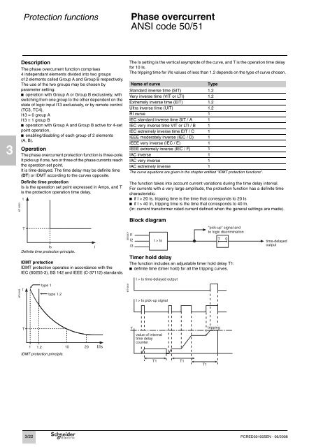
Definite time protection<br />
Is is the operation set point expressed in Amps, and T<br />
is the protection operation time delay.<br />
MT10533<br />
MT10903<br />
t<br />
T<br />
Is<br />
Definite time protection principle.<br />
IDMT protection<br />
IDMT protection operates in accordance with the<br />
IEC (60255-3), BS 142 and IEEE (C-37112) standards.<br />
t<br />
T<br />
1<br />
3/22<br />
type 1<br />
type 1.2<br />
1.2 10 <strong>20</strong> I/Is<br />
IDMT protection principle.<br />
I<br />
The Is setting is the vertical asymptote of the curve, and T is the operation time delay<br />
for 10 Is.<br />
The tripping time for I/Is values of less than 1.2 depends on the type of curve chosen.<br />
Name of curve Type<br />
Standard inverse time (SIT) 1.2<br />
Very inverse time (VIT or LTI) 1.2<br />
Extremely inverse time (EIT) 1.2<br />
Ultra inverse time (UIT) 1.2<br />
RI curve 1<br />
IEC standard inverse time SIT / A 1<br />
IEC very inverse time VIT or LTI / B 1<br />
IEC extremely inverse time EIT / C 1<br />
IEEE moderately inverse (IEC / D) 1<br />
IEEE very inverse (IEC / E) 1<br />
IEEE extremely inverse (IEC / F) 1<br />
IAC inverse 1<br />
IAC very inverse 1<br />
IAC extremely inverse 1<br />
The curve equations are given in the chapter entitled "IDMT protection functions".<br />
DE50371<br />
MT10541<br />
The function takes into account current variations during the time delay interval.<br />
For currents with a very large amplitude, the protection function has a definite time<br />
characteristic:<br />
b if I > <strong>20</strong> Is, tripping time is the time that corresponds to <strong>20</strong> Is<br />
b if I > 40 In, tripping time is the time that corresponds to 40 In.<br />
(In: current transformer rated current defined when the general settings are made).<br />
Block diagram<br />
Timer hold delay<br />
The function includes an adjustable timer hold delay T1:<br />
b definite time (timer hold) for all the tripping curves.<br />
T<br />
I > Is time-delayed output<br />
I > Is pick-up signal<br />
value of internal<br />
time delay<br />
counter<br />
T1 T1<br />
T1<br />
tripping<br />
PCRED301005EN - 06/<strong>20</strong>08


