Models 5E, 5F, 5G & 5H Electric Switch Machines: Single ... - Alstom
Models 5E, 5F, 5G & 5H Electric Switch Machines: Single ... - Alstom
Models 5E, 5F, 5G & 5H Electric Switch Machines: Single ... - Alstom
You also want an ePaper? Increase the reach of your titles
YUMPU automatically turns print PDFs into web optimized ePapers that Google loves.
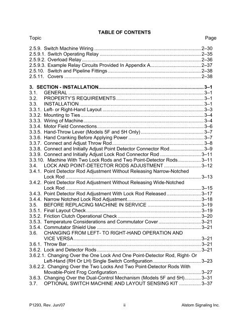
TopicTABLE OF CONTENTSPage2.5.9. <strong>Switch</strong> Machine Wiring ..............................................................................2–302.5.9.1. <strong>Switch</strong> Operating Relay ..........................................................................2–352.5.9.2. Overload Relay .......................................................................................2–362.5.9.3. Example Relay Circuits Provided In Appendix A.....................................2–372.5.10. <strong>Switch</strong> and Pipeline Fittings ....................................................................2–382.5.11. Covers ....................................................................................................2–383. SECTION - INSTALLATION.............................................................................3–13.1. GENERAL ...................................................................................................3–13.2. PROPERTY’S REQUIREMENTS................................................................3–13.3. INSTALLATION ...........................................................................................3–13.3.1. Left- or Right-Hand Layout ..........................................................................3–33.3.2. Mounting to Ties ..........................................................................................3–43.3.3. Wiring of Machine........................................................................................3–43.3.4. Motor Field Connections..............................................................................3–63.3.5. Hand-Throw Lever (<strong>Models</strong> <strong>5F</strong> and <strong>5H</strong> Only)..............................................3–73.3.6. Hand Cranking Before Applying Power .......................................................3–73.3.7. Connect and Adjust Throw Rod...................................................................3–83.3.8. Connect and Initially Adjust Point Detector Connector Rod.........................3–93.3.9. Connect and Initially Adjust Lock Rod Connector Rod ..............................3–113.3.10. Machine With Two Lock Rods and Two Point-Detector Rods.................3–113.4. LOCK AND POINT-DETECTOR RODS ADJUSTMENT ...........................3–123.4.1. Point Detector Rod Adjustment Without Releasing Narrow-NotchedLock Rod ...................................................................................................3–133.4.2. Point Detector Rod Adjustment Without Releasing Wide-NotchedLock Rod ...................................................................................................3–153.4.3. Point Detector Rod Adjustment With Lock Rod Released .........................3–173.4.4. Narrow Notched Lock Rod Adjustment......................................................3–183.5. BEFORE REPLACING MACHINE IN SERVICE .......................................3–193.5.1. Final Layout Check....................................................................................3–193.5.2. Friction Clutch Operational Check .............................................................3–203.5.3. Temperature Considerations and Commutator Cover ...............................3–213.5.4. Commutator Shield Use ............................................................................3–213.6. CHANGING FROM LEFT- TO RIGHT-HAND OPERATION ANDVICE VERSA .............................................................................................3–213.6.1. Throw Bar..................................................................................................3–213.6.2. Lock and Detector Rods ............................................................................3–213.6.2.1. Changing Over the One Lock And One Point-Detector Rod, Right- OrLeft-Hand (RH Or LH) <strong>Single</strong> <strong>Switch</strong> Configuration ...................................3–233.6.2.2. Changing Over the Two Locks And Two Point-Detector Rods WithMovable-Point Frog Configuration .............................................................3–273.6.3. Changing Over the Dual-Control Mechanism (<strong>Models</strong> <strong>5F</strong> and <strong>5H</strong>)............3–313.7. OPTIONAL SWITCH MACHINE AND LAYOUT SENSING KIT ................3–37P1293, Rev. Jun/07 ii <strong>Alstom</strong> Signaling Inc.


