- Page 1 and 2:
Models 5E, 5F, 5G &5H Electric Swit
- Page 3 and 4:
LIST OF EFFECTIVE PAGESP1293, Model
- Page 5 and 6:
PREFACENOTICE OF CONFIDENTIAL INFOR
- Page 7 and 8:
ABOUT THE MANUALThis manual is inte
- Page 9 and 10:
MANUAL SPECIAL NOTATIONSIn the Alst
- Page 11 and 12:
TopicTABLE OF CONTENTSPage1. SECTIO
- Page 13 and 14:
TopicTABLE OF CONTENTSPage4. SECTIO
- Page 15 and 16:
TopicTABLE OF CONTENTSPage6.5.32. C
- Page 17 and 18:
DescriptionLIST OF FIGURES (CONT.)P
- Page 19 and 20:
DescriptionLIST OF TABLESPageTable
- Page 21 and 22:
DescriptionLIST OF TABLES (CONT.)Pa
- Page 23 and 24:
General Description1. SECTION 1 - G
- Page 25 and 26:
General Description1.3. MODEL 5E, 5
- Page 27 and 28:
General Description1.4. MODEL 5 SER
- Page 29 and 30:
General DescriptionThe components i
- Page 31 and 32:
General Description1.5.2. Proper At
- Page 33 and 34:
General Description1.5.7. Safety at
- Page 35 and 36:
Theory of Operation2. SECTION 2 - T
- Page 37 and 38:
Theory of OperationFigure 2-3. Hand
- Page 39 and 40:
Theory of OperationFigure 2-5. Inse
- Page 41 and 42:
Theory of OperationThe locations of
- Page 43 and 44:
Theory of Operation2.5.1. MotorThe
- Page 45 and 46:
Theory of Operation2.5.1.1. Commuta
- Page 47 and 48:
Theory of OperationWhen the motor i
- Page 49 and 50:
Theory of OperationTHROWBARHAND CRA
- Page 51 and 52:
Theory of Operation2.5.3.1. Frictio
- Page 53 and 54:
Theory of OperationFinal cam bar mo
- Page 55 and 56:
Theory of Operation2.5.5. Lock RodT
- Page 57 and 58:
Theory of Operation2.5.6. Point Det
- Page 59 and 60:
Theory of Operation2.5.7. Box Style
- Page 61 and 62:
Theory of OperationFigure 2-27. Poi
- Page 63 and 64:
Theory of Operation2.5.8.3. Shunt C
- Page 65 and 66:
Theory of OperationWARNINGADHERE TO
- Page 67 and 68:
Theory of Operation46POINT DETECTOR
- Page 69 and 70:
Theory of Operation2.5.9.1. Switch
- Page 71 and 72:
Theory of Operation2.5.9.3. Example
- Page 73 and 74:
Installation3. SECTION - INSTALLATI
- Page 75 and 76:
Installation3.3.1. Left- or Right-H
- Page 77 and 78:
InstallationMIN. FOR 5E, 5F ONLYFig
- Page 79 and 80:
Installation3.3.5. Hand-Throw Lever
- Page 81 and 82:
Installation3.3.8. Connect and Init
- Page 83 and 84:
Installation3.3.9. Connect and Init
- Page 85 and 86:
Installation3.4.1. Point Detector R
- Page 87 and 88: Installation3.4.2. Point Detector R
- Page 89 and 90: Installation3.4.3. Point Detector R
- Page 91 and 92: Installation3.5. BEFORE REPLACING M
- Page 93 and 94: Installation3.5.3. Temperature Cons
- Page 95 and 96: Installation3.6.2.1. Changing Over
- Page 97 and 98: InstallationTable 3-12. Changing Ov
- Page 99 and 100: Installation3.6.2.2. Changing Over
- Page 101 and 102: InstallationTable 3-13. Changing Ov
- Page 103 and 104: Installation3.6.3. Changing Over th
- Page 105 and 106: InstallationTable 3-14. Changing Ov
- Page 107 and 108: InstallationFigure 3-5. 5H Switch M
- Page 109 and 110: InstallationTable 3-15. Throw Rod P
- Page 111 and 112: InstallationTHIS PAGE INTENTIONALLY
- Page 113 and 114: Scheduled Maintenance4.4. SPECIAL T
- Page 115 and 116: Scheduled Maintenance4.6. PREVENTIV
- Page 117 and 118: Scheduled MaintenanceTable 4-2. Sit
- Page 119 and 120: Scheduled MaintenanceTable 4-3. Lub
- Page 121 and 122: Scheduled MaintenanceOIL PER ALSTOM
- Page 123 and 124: Scheduled MaintenanceOIL PER ALSTOM
- Page 125 and 126: Scheduled Maintenance4.9. QUARTERLY
- Page 127 and 128: Scheduled MaintenanceTable 4-8. Obs
- Page 129 and 130: Scheduled Maintenance4.9.3. Motor B
- Page 131 and 132: Scheduled Maintenance4.9.4. Box-Sty
- Page 133 and 134: Scheduled MaintenanceTable 4-11. Bo
- Page 135 and 136: Scheduled MaintenanceTable 4-12. Th
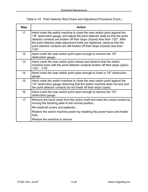
- Page 137: Scheduled MaintenanceTable 4-13. Lo
- Page 141 and 142: Scheduled MaintenanceTable 4-15. Po
- Page 143 and 144: Scheduled Maintenance4.9.9. Shunt C
- Page 145 and 146: Scheduled Maintenance4.9.9.2. Model
- Page 147 and 148: Scheduled MaintenanceTable 4-18. Mo
- Page 149 and 150: Scheduled MaintenanceTable 4-19. Co
- Page 151 and 152: Scheduled Maintenance4.9.12. Fricti
- Page 153 and 154: Scheduled Maintenance4.9.13. Fricti
- Page 155 and 156: Scheduled Maintenance4.9.14. Fricti
- Page 157 and 158: Scheduled Maintenance4.9.15. Crank
- Page 159 and 160: Scheduled Maintenance4.10. SEMI-ANN
- Page 161 and 162: Scheduled MaintenanceTable 4-26. Ma
- Page 163 and 164: Scheduled MaintenanceTHIS PAGE INTE
- Page 165 and 166: TroubleshootingTable 5-1. Symptoms
- Page 167 and 168: TroubleshootingTable 5-2. Trackside
- Page 169 and 170: Corrective Maintenance6.2. TEST EQU
- Page 171 and 172: Corrective MaintenanceTable 6-2. Sw
- Page 173 and 174: Corrective MaintenanceTable 6-3. Sw
- Page 175 and 176: Corrective MaintenanceTable 6-6. Cl
- Page 177 and 178: Corrective Maintenance6.4.1. Switch
- Page 179 and 180: Corrective MaintenanceTable 6-7. Sw
- Page 181 and 182: Corrective MaintenanceTable 6-7. Sw
- Page 183 and 184: Corrective MaintenanceTable 6-7. Sw
- Page 185 and 186: Corrective MaintenanceTable 6-7. Sw
- Page 187 and 188: Corrective MaintenanceTable 6-7. Sw
- Page 189 and 190:
Corrective MaintenanceTable 6-7. Sw
- Page 191 and 192:
Corrective MaintenanceTable 6-7. Sw
- Page 193 and 194:
Corrective MaintenanceTable 6-7. Sw
- Page 195 and 196:
Corrective MaintenanceTable 6-7. Sw
- Page 197 and 198:
Corrective MaintenanceTable 6-7. Sw
- Page 199 and 200:
Corrective MaintenanceTable 6-7. Sw
- Page 201 and 202:
Corrective MaintenanceTable 6-7. Sw
- Page 203 and 204:
Corrective Maintenance6.4.2. MotorT
- Page 205 and 206:
Corrective MaintenanceTable 6-8. Mo
- Page 207 and 208:
Corrective MaintenanceTable 6-8. Mo
- Page 209 and 210:
Corrective MaintenanceTable 6-8. Mo
- Page 211 and 212:
Corrective MaintenanceTable 6-8. Mo
- Page 213 and 214:
Corrective MaintenanceTable 6-8. Mo
- Page 215 and 216:
Corrective MaintenanceTable 6-8. Mo
- Page 217 and 218:
Corrective MaintenanceTable 6-8. Mo
- Page 219 and 220:
Corrective Maintenance6.4.3. Clutch
- Page 221 and 222:
Corrective Maintenance6.4.4. Point
- Page 223 and 224:
Corrective MaintenanceTable 6-10. P
- Page 225 and 226:
Corrective MaintenanceTable 6-12. C
- Page 227 and 228:
Corrective Maintenance6.5.2. Brush
- Page 229 and 230:
Corrective Maintenance6.5.4. Motor
- Page 231 and 232:
Corrective Maintenance6.5.6. Motor
- Page 233 and 234:
Corrective Maintenance6.5.8. Throw
- Page 235 and 236:
Corrective Maintenance6.5.12. Lock
- Page 237 and 238:
Corrective Maintenance6.5.14. Cutou
- Page 239 and 240:
Corrective Maintenance6.5.17. Inter
- Page 241 and 242:
Corrective Maintenance6.5.19. Recti
- Page 243 and 244:
Corrective Maintenance6.5.22. Conta
- Page 245 and 246:
Corrective Maintenance6.5.24. Arm (
- Page 247 and 248:
Corrective Maintenance6.5.27. Throw
- Page 249 and 250:
Corrective Maintenance6.5.31. Cam B
- Page 251 and 252:
Corrective Maintenance6.6. SWITCH M
- Page 253 and 254:
Corrective MaintenanceTable 6-47. M
- Page 255 and 256:
Corrective MaintenanceTable 6-47. M
- Page 257 and 258:
Corrective MaintenanceTable 6-47. M
- Page 259 and 260:
Corrective MaintenanceTable 6-47. M
- Page 261 and 262:
Corrective MaintenanceTable 6-47. M
- Page 263 and 264:
Corrective MaintenanceTable 6-47. M
- Page 265 and 266:
Corrective MaintenanceTHIS PAGE INT
- Page 267 and 268:
Parts CatalogFigure 7-1. Model 5E S
- Page 269 and 270:
Parts CatalogTable 7-1. Main Parts
- Page 271 and 272:
Parts CatalogFigure 7-3. Model 5F S
- Page 273 and 274:
Parts CatalogTable 7-2. Main Parts
- Page 275 and 276:
Parts CatalogFigure 7-5. Detail Par
- Page 277 and 278:
Parts CatalogTable 7-3. Detail Part
- Page 279 and 280:
Parts CatalogTable 7-3. Detail Part
- Page 281 and 282:
Parts CatalogFigure 7-6. Bars, Coup
- Page 283 and 284:
Parts CatalogFigure 7-7. Brackets,
- Page 285 and 286:
Parts CatalogTable 7-5. Brackets, P
- Page 287 and 288:
Parts CatalogTable 7-6. Selector-Le
- Page 289 and 290:
Parts CatalogTable 7-6. Selector-Le
- Page 291 and 292:
Parts CatalogFigure 7-9. FramesP129
- Page 293 and 294:
Parts CatalogTable 7-7. Frames (Con
- Page 295 and 296:
Parts CatalogTable 7-7. Frames (Con
- Page 297 and 298:
Parts CatalogFigure 7-10. Point-Det
- Page 299 and 300:
Parts CatalogTable 7-8. Point-Detec
- Page 301 and 302:
Parts CatalogFigure 7-11. Lock Rods
- Page 303 and 304:
Parts Catalog67381245ALink MotionFi
- Page 305 and 306:
Parts CatalogFigure 7-13. Biased-Ne
- Page 307 and 308:
Parts CatalogTable 7-11. Biased-Neu
- Page 309 and 310:
Parts CatalogFigure 7-14. Contactor
- Page 311 and 312:
Parts CatalogTable 7-12. Contactor
- Page 313 and 314:
Parts CatalogTable 7-12. Contactor
- Page 315 and 316:
Parts CatalogTable 7-13. Switch Mac
- Page 317 and 318:
Parts CatalogTable 7-13. Switch Mac
- Page 319 and 320:
Parts CatalogTable 7-14. Terminal B
- Page 321 and 322:
Parts CatalogTable 7-15. Wire Entra
- Page 323 and 324:
Parts CatalogTable 7-16. ToolsRefNo
- Page 325 and 326:
DrawingsNWRLRWZR6POINT DETECTOR(NOT
- Page 327 and 328:
DrawingsPOINT DETECTORD8 7 6 5 4 3
- Page 329 and 330:
DrawingsPOINT DETECTORD8 7 6 5 4 3
- Page 331 and 332:
DrawingsTERMINAL BOARDR.H. POINTNOR
- Page 333 and 334:
DrawingsTERMINAL BOARD1 2 3 4 5 6 7
- Page 335:
DrawingsTHIS PAGE INTENTIONALLY LEF