Models 5E, 5F, 5G & 5H Electric Switch Machines: Single ... - Alstom
Models 5E, 5F, 5G & 5H Electric Switch Machines: Single ... - Alstom
Models 5E, 5F, 5G & 5H Electric Switch Machines: Single ... - Alstom
Create successful ePaper yourself
Turn your PDF publications into a flip-book with our unique Google optimized e-Paper software.
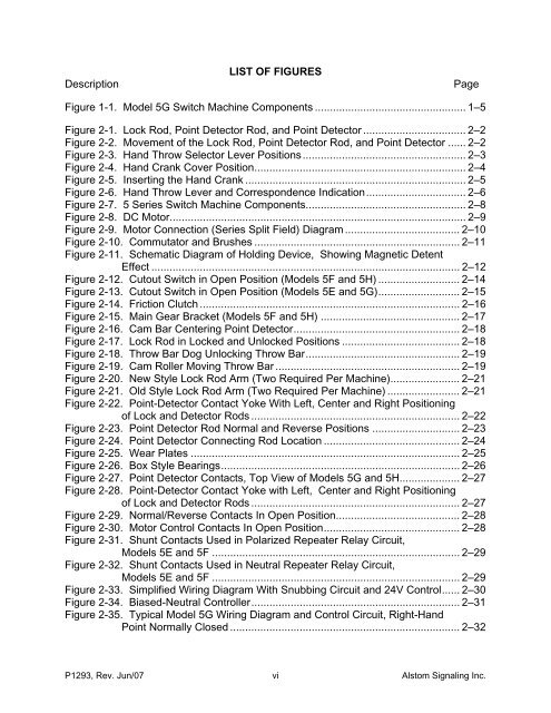
DescriptionLIST OF FIGURESPageFigure 1-1. Model <strong>5G</strong> <strong>Switch</strong> Machine Components .................................................. 1–<strong>5F</strong>igure 2-1. Lock Rod, Point Detector Rod, and Point Detector .................................. 2–2Figure 2-2. Movement of the Lock Rod, Point Detector Rod, and Point Detector ...... 2–2Figure 2-3. Hand Throw Selector Lever Positions...................................................... 2–3Figure 2-4. Hand Crank Cover Position...................................................................... 2–4Figure 2-5. Inserting the Hand Crank ......................................................................... 2–<strong>5F</strong>igure 2-6. Hand Throw Lever and Correspondence Indication................................. 2–6Figure 2-7. 5 Series <strong>Switch</strong> Machine Components..................................................... 2–8Figure 2-8. DC Motor.................................................................................................. 2–9Figure 2-9. Motor Connection (Series Split Field) Diagram ...................................... 2–10Figure 2-10. Commutator and Brushes .................................................................... 2–11Figure 2-11. Schematic Diagram of Holding Device, Showing Magnetic DetentEffect ...................................................................................................... 2–12Figure 2-12. Cutout <strong>Switch</strong> in Open Position (<strong>Models</strong> <strong>5F</strong> and <strong>5H</strong>) ........................... 2–14Figure 2-13. Cutout <strong>Switch</strong> in Open Position (<strong>Models</strong> <strong>5E</strong> and <strong>5G</strong>)........................... 2–1<strong>5F</strong>igure 2-14. Friction Clutch ...................................................................................... 2–16Figure 2-15. Main Gear Bracket (<strong>Models</strong> <strong>5F</strong> and <strong>5H</strong>) .............................................. 2–17Figure 2-16. Cam Bar Centering Point Detector....................................................... 2–18Figure 2-17. Lock Rod in Locked and Unlocked Positions ....................................... 2–18Figure 2-18. Throw Bar Dog Unlocking Throw Bar................................................... 2–19Figure 2-19. Cam Roller Moving Throw Bar ............................................................. 2–19Figure 2-20. New Style Lock Rod Arm (Two Required Per Machine)....................... 2–21Figure 2-21. Old Style Lock Rod Arm (Two Required Per Machine) ........................ 2–21Figure 2-22. Point-Detector Contact Yoke With Left, Center and Right Positioningof Lock and Detector Rods ..................................................................... 2–22Figure 2-23. Point Detector Rod Normal and Reverse Positions ............................. 2–23Figure 2-24. Point Detector Connecting Rod Location ............................................. 2–24Figure 2-25. Wear Plates ......................................................................................... 2–2<strong>5F</strong>igure 2-26. Box Style Bearings............................................................................... 2–26Figure 2-27. Point Detector Contacts, Top View of <strong>Models</strong> <strong>5G</strong> and <strong>5H</strong>.................... 2–27Figure 2-28. Point-Detector Contact Yoke with Left, Center and Right Positioningof Lock and Detector Rods ..................................................................... 2–27Figure 2-29. Normal/Reverse Contacts In Open Position......................................... 2–28Figure 2-30. Motor Control Contacts In Open Position............................................. 2–28Figure 2-31. Shunt Contacts Used in Polarized Repeater Relay Circuit,<strong>Models</strong> <strong>5E</strong> and <strong>5F</strong> .................................................................................. 2–29Figure 2-32. Shunt Contacts Used in Neutral Repeater Relay Circuit,<strong>Models</strong> <strong>5E</strong> and <strong>5F</strong> .................................................................................. 2–29Figure 2-33. Simplified Wiring Diagram With Snubbing Circuit and 24V Control...... 2–30Figure 2-34. Biased-Neutral Controller..................................................................... 2–31Figure 2-35. Typical Model <strong>5G</strong> Wiring Diagram and Control Circuit, Right-HandPoint Normally Closed ............................................................................ 2–32P1293, Rev. Jun/07 vi <strong>Alstom</strong> Signaling Inc.


