

Models 5E, 5F, 5G & 5H Electric Switch Machines: Single ... - Alstom
Models 5E, 5F, 5G & 5H Electric Switch Machines: Single ... - Alstom
Models 5E, 5F, 5G & 5H Electric Switch Machines: Single ... - Alstom

Create successful ePaper yourself
Turn your PDF publications into a flip-book with our unique Google optimized e-Paper software.
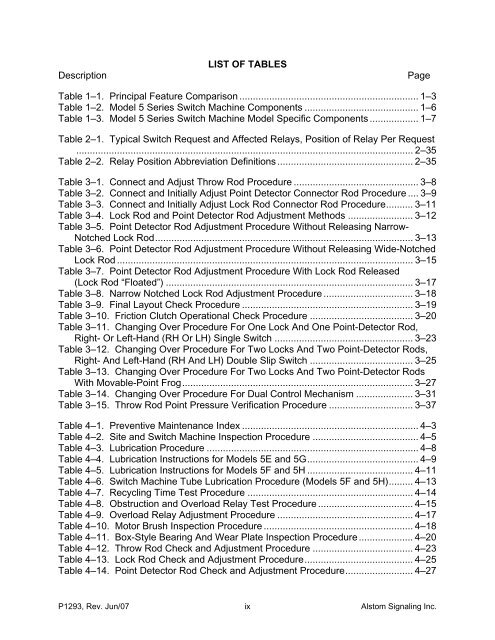
DescriptionLIST OF TABLESPageTable 1–1. Principal Feature Comparison .................................................................. 1–3Table 1–2. Model 5 Series <strong>Switch</strong> Machine Components .......................................... 1–6Table 1–3. Model 5 Series <strong>Switch</strong> Machine Model Specific Components .................. 1–7Table 2–1. Typical <strong>Switch</strong> Request and Affected Relays, Position of Relay Per Request............................................................................................................................ 2–35Table 2–2. Relay Position Abbreviation Definitions .................................................. 2–35Table 3–1. Connect and Adjust Throw Rod Procedure .............................................. 3–8Table 3–2. Connect and Initially Adjust Point Detector Connector Rod Procedure .... 3–9Table 3–3. Connect and Initially Adjust Lock Rod Connector Rod Procedure.......... 3–11Table 3–4. Lock Rod and Point Detector Rod Adjustment Methods ........................ 3–12Table 3–5. Point Detector Rod Adjustment Procedure Without Releasing Narrow-Notched Lock Rod............................................................................................... 3–13Table 3–6. Point Detector Rod Adjustment Procedure Without Releasing Wide-NotchedLock Rod ............................................................................................................. 3–15Table 3–7. Point Detector Rod Adjustment Procedure With Lock Rod Released(Lock Rod “Floated”) ........................................................................................... 3–17Table 3–8. Narrow Notched Lock Rod Adjustment Procedure ................................. 3–18Table 3–9. Final Layout Check Procedure ............................................................... 3–19Table 3–10. Friction Clutch Operational Check Procedure ...................................... 3–20Table 3–11. Changing Over Procedure For One Lock And One Point-Detector Rod,Right- Or Left-Hand (RH Or LH) <strong>Single</strong> <strong>Switch</strong> ................................................... 3–23Table 3–12. Changing Over Procedure For Two Locks And Two Point-Detector Rods,Right- And Left-Hand (RH And LH) Double Slip <strong>Switch</strong> ...................................... 3–25Table 3–13. Changing Over Procedure For Two Locks And Two Point-Detector RodsWith Movable-Point Frog..................................................................................... 3–27Table 3–14. Changing Over Procedure For Dual Control Mechanism ..................... 3–31Table 3–15. Throw Rod Point Pressure Verification Procedure ............................... 3–37Table 4–1. Preventive Maintenance Index ................................................................. 4–3Table 4–2. Site and <strong>Switch</strong> Machine Inspection Procedure ....................................... 4–5Table 4–3. Lubrication Procedure .............................................................................. 4–8Table 4–4. Lubrication Instructions for <strong>Models</strong> <strong>5E</strong> and <strong>5G</strong>......................................... 4–9Table 4–5. Lubrication Instructions for <strong>Models</strong> <strong>5F</strong> and <strong>5H</strong> ....................................... 4–11Table 4–6. <strong>Switch</strong> Machine Tube Lubrication Procedure (<strong>Models</strong> <strong>5F</strong> and <strong>5H</strong>)......... 4–13Table 4–7. Recycling Time Test Procedure ............................................................. 4–14Table 4–8. Obstruction and Overload Relay Test Procedure ................................... 4–15Table 4–9. Overload Relay Adjustment Procedure .................................................. 4–17Table 4–10. Motor Brush Inspection Procedure ....................................................... 4–18Table 4–11. Box-Style Bearing And Wear Plate Inspection Procedure .................... 4–20Table 4–12. Throw Rod Check and Adjustment Procedure ..................................... 4–23Table 4–13. Lock Rod Check and Adjustment Procedure........................................ 4–25Table 4–14. Point Detector Rod Check and Adjustment Procedure......................... 4–27P1293, Rev. Jun/07 ix <strong>Alstom</strong> Signaling Inc.


