

Models 5E, 5F, 5G & 5H Electric Switch Machines: Single ... - Alstom
Models 5E, 5F, 5G & 5H Electric Switch Machines: Single ... - Alstom
Models 5E, 5F, 5G & 5H Electric Switch Machines: Single ... - Alstom

You also want an ePaper? Increase the reach of your titles
YUMPU automatically turns print PDFs into web optimized ePapers that Google loves.
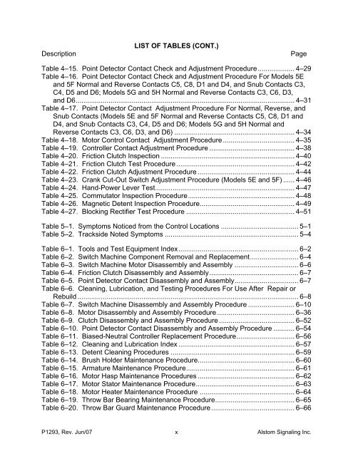
DescriptionLIST OF TABLES (CONT.)PageTable 4–15. Point Detector Contact Check and Adjustment Procedure................... 4–29Table 4–16. Point Detector Contact Check and Adjustment Procedure For <strong>Models</strong> <strong>5E</strong>and <strong>5F</strong> Normal and Reverse Contacts C5, C8, D1 and D4, and Snub Contacts C3,C4, D5 and D6; <strong>Models</strong> <strong>5G</strong> and <strong>5H</strong> Normal and Reverse Contacts C3, C6, D3,and D6................................................................................................................. 4–31Table 4–17. Point Detector Contact Adjustment Procedure For Normal, Reverse, andSnub Contacts (<strong>Models</strong> <strong>5E</strong> and <strong>5F</strong> Normal and Reverse Contacts C5, C8, D1 andD4, and Snub Contacts C3, C4, D5 and D6; <strong>Models</strong> <strong>5G</strong> and <strong>5H</strong> Normal andReverse Contacts C3, C6, D3, and D6) .............................................................. 4–34Table 4–18. Motor Control Contact Adjustment Procedure ..................................... 4–35Table 4–19. Controller Contact Adjustment Procedure ............................................ 4–38Table 4–20. Friction Clutch Inspection ..................................................................... 4–40Table 4–21. Friction Clutch Test Procedure ............................................................. 4–42Table 4–22. Friction Clutch Adjustment Procedure .................................................. 4–44Table 4–23. Crank Cut-Out <strong>Switch</strong> Adjustment Procedure (<strong>Models</strong> <strong>5E</strong> and <strong>5F</strong>) ...... 4–46Table 4–24. Hand-Power Lever Test........................................................................ 4–47Table 4–25. Commutator Inspection Procedure....................................................... 4–48Table 4–26. Magnetic Detent Inspection Procedure................................................. 4–49Table 4–27. Blocking Rectifier Test Procedure ........................................................ 4–51Table 5–1. Symptoms Noticed from the Control Locations ........................................ 5–1Table 5–2. Trackside Noted Symptoms ..................................................................... 5–4Table 6–1. Tools and Test Equipment Index.............................................................. 6–2Table 6–2. <strong>Switch</strong> Machine Component Removal and Replacement......................... 6–4Table 6–3. <strong>Switch</strong> Machine Motor Disassembly and Assembly ................................. 6–6Table 6–4. Friction Clutch Disassembly and Assembly.............................................. 6–7Table 6–5. Point Detector Contact Disassembly and Assembly................................. 6–7Table 6–6. Cleaning, Lubrication, and Testing Procedures For Use After Repair orRebuild .................................................................................................................. 6–8Table 6–7. <strong>Switch</strong> Machine Disassembly and Assembly Procedure ........................ 6–10Table 6–8. Motor Disassembly and Assembly Procedure ........................................ 6–36Table 6–9. Clutch Disassembly and Assembly Procedure ....................................... 6–52Table 6–10. Point Detector Contact Disassembly and Assembly Procedure ........... 6–54Table 6–11. Biased-Neutral Controller Replacement Procedure.............................. 6–56Table 6–12. Cleaning and Lubrication Index ............................................................ 6–57Table 6–13. Detent Cleaning Procedures ................................................................ 6–59Table 6–14. Brush Holder Maintenance Procedure.................................................. 6–60Table 6–15. Armature Maintenance Procedure........................................................ 6–61Table 6–16. Motor Hasp Maintenance Procedures .................................................. 6–62Table 6–17. Motor Stator Maintenance Procedure................................................... 6–63Table 6–18. Motor Heater Maintenance Procedure ................................................. 6–64Table 6–19. Throw Bar Bearing Maintenance Procedure......................................... 6–65Table 6–20. Throw Bar Guard Maintenance Procedure ........................................... 6–66P1293, Rev. Jun/07 x <strong>Alstom</strong> Signaling Inc.


