DS7200V2-EXP - Simon Technologies
DS7200V2-EXP - Simon Technologies
DS7200V2-EXP - Simon Technologies

Create successful ePaper yourself
Turn your PDF publications into a flip-book with our unique Google optimized e-Paper software.
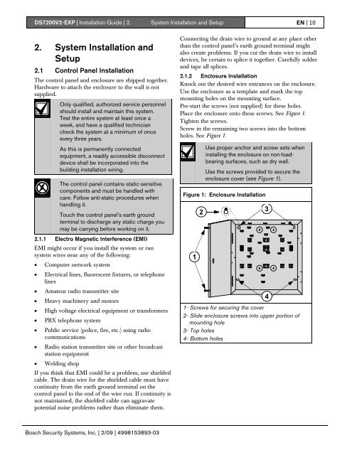
<strong>DS7200V2</strong>-<strong>EXP</strong> | Installation Guide | 2. System Installation and Setup EN | 102. System Installation andSetup2.1 Control Panel InstallationThe control panel and enclosure are shipped together.Hardware to attach the enclosure to the wall is notsupplied.Only qualified, authorized service personnelshould install and maintain this system.Test the entire system at least once aweek, and have a qualified techniciancheck the system at a minimum of onceevery three years.As this is permanently connectedequipment, a readily accessible disconnectdevice shall be incorporated into thebuilding installation wiring.The control panel contains static-sensitivecomponents and must be handled withcare. Follow anti-static procedures whenhandling it.Touch the control panel’s earth groundterminal to discharge any static charge youmay be carrying before working on it.2.1.1 Electro Magnetic Interference (EMI)EMI might occur if you install the system or runsystem wires near any of the following:• Computer network system• Electrical lines, fluorescent fixtures, or telephonelines• Amateur radio transmitter site• Heavy machinery and motors• High voltage electrical equipment or transformers• PBX telephone system• Public service (police, fire, etc.) using radiocommunications• Radio station transmitter site or other broadcaststation equipment• Welding shopIf you think that EMI could be a problem, use shieldedcable. The drain wire for the shielded cable must havecontinuity from the earth ground terminal on thecontrol panel to the end of the wire run. If continuity isnot maintained, the shielded cable can aggravatepotential noise problems rather than eliminate them.Connecting the drain wire to ground at any place otherthan the control panel’s earth ground terminal mightalso create problems. If you cut the drain wire to installdevices, be certain to splice it together. Carefully solderand tape all splices.2.1.2 Enclosure InstallationKnock out the desired wire entrances on the enclosure.Use the enclosure as a template and mark the topmounting holes on the mounting surface.Pre-start the screws (not supplied) for these holes.Place the enclosure onto these screws. See Figure 1.Tighten the screws.Screw in the remaining two screws into the bottomholes. See Figure 1.Use proper anchor and screw sets wheninstalling the enclosure on non-loadbearingsurfaces, such as dry wall.Use the screws provided to secure theenclosure cover (see Figure 1).Figure 1: Enclosure Installation121- Screws for securing the cover2- Slide enclosure screws into upper portion ofmounting hole3- Top holes4- Bottom holes34Bosch Security Systems, Inc. | 2/09 | 4998153893-03