DS7200V2-EXP - Simon Technologies
DS7200V2-EXP - Simon Technologies
DS7200V2-EXP - Simon Technologies

Create successful ePaper yourself
Turn your PDF publications into a flip-book with our unique Google optimized e-Paper software.
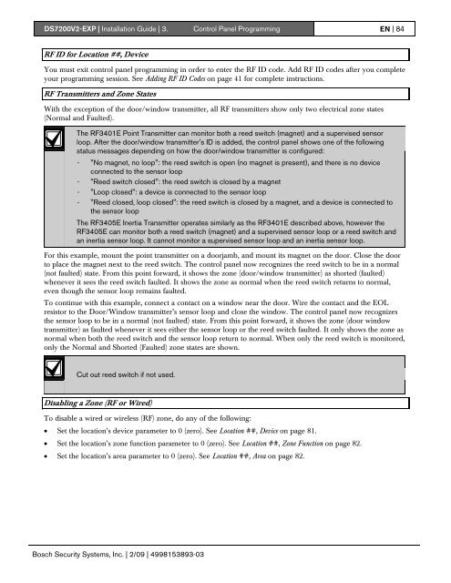
<strong>DS7200V2</strong>-<strong>EXP</strong> | Installation Guide | 3. Control Panel Programming EN | 84RF ID for Location ##, DeviceYou must exit control panel programming in order to enter the RF ID code. Add RF ID codes after you completeyour programming session. See Adding RF ID Codes on page 41 for complete instructions.RF Transmitters and Zone StatesWith the exception of the door/window transmitter, all RF transmitters show only two electrical zone states(Normal and Faulted).The RF3401E Point Transmitter can monitor both a reed switch (magnet) and a supervised sensorloop. After the door/window transmitter's ID is added, the control panel shows one of the followingstatus messages depending on how the door/window transmitter is configured:- "No magnet, no loop": the reed switch is open (no magnet is present), and there is no deviceconnected to the sensor loop- "Reed switch closed": the reed switch is closed by a magnet- "Loop closed": a device is connected to the sensor loop- "Reed closed, loop closed": the reed switch is closed by a magnet, and a device is connected tothe sensor loopThe RF3405E Inertia Transmitter operates similarly as the RF3401E described above, however theRF3405E can monitor both a reed switch (magnet) and a supervised sensor loop or a reed switch andan inertia sensor loop. It cannot monitor a supervised sensor loop and an inertia sensor loop.For this example, mount the point transmitter on a doorjamb, and mount its magnet on the door. Close the doorto place the magnet next to the reed switch. The control panel now recognizes the reed switch to be in a normal(not faulted) state. From this point forward, it shows the zone (door/window transmitter) as shorted (faulted)whenever it sees the reed switch faulted. It shows the zone as normal when the reed switch returns to normal,even though the sensor loop remains faulted.To continue with this example, connect a contact on a window near the door. Wire the contact and the EOLresistor to the Door/Window transmitter’s sensor loop and close the window. The control panel now recognizesthe sensor loop to be in a normal (not faulted) state. From this point forward, it shows the zone (door windowtransmitter) as faulted whenever it sees either the sensor loop or the reed switch faulted. It only shows the zone asnormal when both the reed switch and the sensor loop return to normal. When only the reed switch is monitored,only the Normal and Shorted (Faulted) zone states are shown.Cut out reed switch if not used.Disabling a Zone (RF or Wired)To disable a wired or wireless (RF) zone, do any of the following:• Set the location’s device parameter to 0 (zero). See Location ##, Device on page 81.• Set the location’s zone function parameter to 0 (zero). See Location ##, Zone Function on page 82.• Set the location’s area parameter to 0 (zero). See Location ##, Area on page 82.Bosch Security Systems, Inc. | 2/09 | 4998153893-03