DS7200V2-EXP - Simon Technologies
DS7200V2-EXP - Simon Technologies
DS7200V2-EXP - Simon Technologies

Create successful ePaper yourself
Turn your PDF publications into a flip-book with our unique Google optimized e-Paper software.
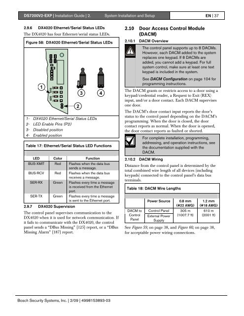
<strong>DS7200V2</strong>-<strong>EXP</strong> | Installation Guide | 2. System Installation and Setup EN | 372.9.6 DX4020 Ethernet/Serial Status LEDsThe DX4020 has four Ethernet/serial status LEDs.Figure 58: DX4020 Ethernet/Serial Status LEDs123 41- DX4020 Ethernet/Serial Status LEDs2- LED Enable Pins (P2)3- Disabled position4- Enabled positionTable 17: Ethernet/Serial Status LED FunctionsLED Color FunctionBUS-XMIT Red Flashes when the data bussends a message.BUS-RCV Red Flashes when the data busreceives a message.SER-RX Green Flashes every time a messageis received from the Ethernetport.SER-TX Green Flashes every time a messageis sent to the Ethernet port.2.9.7 DX4020 SupervisionThe control panel supervises communication to theDX4020 when it is used for network communication. Ifit fails to communicate with the DX4020, the controlpanel sends a “DBus Missing” {125} report, or a “DBusMissing Alarm” {187} report.2.10 Door Access Control Module(DACM)2.10.1 DACM OverviewThe control panel supports up to 8 DACMs.However, each DACM added to the systemreplaces one keypad. If 8 DACMs areadded, you cannot add a keypad. For fullsystem control, make sure at least one textkeypad is included in the system.See DACM Configuration on page 104 forprogramming instructions.The DACM grants or restricts access to a door using akeypad/credential reader, a Request to Exit (REX)input, and/or a door contact. Each DACM supervisesone door.The DACM’s door contact input reports the door’sstatus to the control panel depending on the DACM’sprogramming. When the door is closed, the doorcontact reports as normal. When the door is opened,the door contact reports as faulted or shorted.For complete installation, programming,addressing, and operation instructions, seethe documentation supplied with theDACM.2.10.2 DACM WiringDistance from the control panel is determined by thetotal combined wire length of all devices (includingkeypads) connected to the control panel’s data busterminals.Table 18: DACM Wire LengthsDACM toControlPanelPower SourceControl PanelExternal PowerSupply0.8 mm(#22 AWG)305 m(1007.7 ft)1.2 mm(#18 AWG)610 m(2001 ft)See Figure 59, on page 38, and Figure 60, on page 38,for acceptable power wiring connections.Bosch Security Systems, Inc. | 2/09 | 4998153893-03