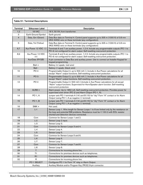
<strong>DS7200V2</strong>-<strong>EXP</strong> | Installation Guide | 4. Reference Materials EN | 128Table 51: Terminal DescriptionsTerminal Silkscreen Label Description1,2 18 VAC 18 V, 50 VA; from transformer.3 Earth Ground Symbol Earth ground.4 Data, Grn (Green) Data Bus data on Terminal 4. Control panel supports up to 305 m (1000 ft) of 0.8 mm(#22 AWG) wire on these terminals (any configuration).5 Data, Yel (Yellow) Data Bus data on Terminal 5. Control panel supports up to 305 m (1000 ft) of 0.8 mm(#22 AWG) wire on these terminals (any configuration).6,7 Aux Power 12 VDC (-) Terminals 6 and 7 are auxiliary power. 1.2 A. Include any programmable outputs (PO 1 toPO 4) not configured for alarm output. Self-resetting overcurrent protection.8,9 Aux Power 12 VDC(+)Aux/Data (RYGB)Batt +Batt -Terminals 8 and 9 are auxiliary power. 1.2 A. Include any programmable outputs (PO 1 toPO 4) not configured for alarm output. Self-resetting overcurrent protection.4-pin connector to Data Bus and auxiliary power. Use to connect an Installer Keypad forkeypad programming.Battery (+) spade. (red wire)Battery (-) spade. (black wire)10 PO 4 Programmable Output 4, up to 500 mA (-). Include in Aux Power calculations for allexcept “Alarm” output functions. Self-resetting overcurrent protection.11 PO 3 Programmable Output 3, up to 500 mA (-). Include in Aux Power calculations for allexcept “Alarm” output functions. Self-resetting overcurrent protection.12 PO 2 Programmable Output 2. 500 mA (-).Include in Aux Power calculations for all except“Alarm” output functions. Supervised for Horn/Speaker alarm function. Self-resettingovercurrent protection.13 ALRM + Alarm power. Up to 1850 mA. Self-resetting overcurrent protection. Provides power forsupervised siren driver (PO 2) and Alarm Output (PO 1, A).14 PO 1, A Jumper sets PO 1 terminals A (14) and B (15) for “dry” Form “A” contact or for AlarmOutput (using PO 1, A as negative (-) terminal).15 PO 1, B Jumper sets PO 1 terminals A (14) and B (15) for “dry” Form “A” contact or for AlarmOutput (using PO 1, A as negative (-) terminal).16 SMK + Not used.17 L-1 Sensor Loop 1. Wire length for Sensor Loops 1 to 8 are limited only by the resistance onthe loop and potential EMI problems. Resistance must be < 100 Ω with EOL resistorshorted and detection devices connected.18 Com Common for Sensor Loops 1 and 2.19 L-2 Sensor Loop 2 input.20 L-3 Sensor Loop 3.21 Com Common for Sensor Loops 3 and 4.22 L-4 Sensor Loop 4.23 L-5 Sensor Loop 5.24 Com Common for Sensor Loops 5 and 6.25 L-6 Sensor Loop 6.26 L-7 Sensor Loop 7.27 Com Common for Sensor Loops 7 and 8.28 L-8 Sensor Loop 8.29 T Connections for incoming phone line.30 T1 Connections for premises devices such as telephones.31 R1 Connections for premises devices such as telephones.32 R Connections for incoming phone line.PO 1 SELECT Configures PO 1 for Form “A” relay or Alarm Output.Auxiliary Auxiliary Module and/or Program Key (PK32) 8-pin connector.Bosch Security Systems, Inc. | 2/09 | 4998153893-03
<strong>DS7200V2</strong>-<strong>EXP</strong> | Installation Guide | 4. Reference Materials EN | 1294.10 Glossary24-Hour Zone:Account Number:Address:All On:Area (Partition):ARC:Authority Level:Burg Alarm Tone:Bypass:Checksum:Cross Zone:DACM:Data Digit:Duress PIN:Entry Delay:Error Tone:Faulted Zone:Fire Alarm Tone:Follower Zone:Force Arming:Global:Groups:Handshake:Hold:Instant Alarm:Keyfob:Zones that are always on even when the system is turned off. Two types: Fire Zones and Non-Fire Zones.The account number is the number the control panel transmits to the ARC receiver. It is not the PersonalIdentification Number (PIN). The account number is not sufficient identification to abort an alarm.Once the installer selects a value for a parameter, the control panel stores the selection in memory. Eachparameter uses one or more Addresses. When programming from the keypad, the installer enters aselection directly into the memory Address(es). When programming from the remote programmer, theinstaller need only make one entry per parameter.All zones are armed. All On with No Entry (Instant) is an option.An installer-specified collection of zones that can be armed and disarmed independently. An Area canreport with its own account number. Opening, closing, alarm, trouble and restoral reports are all associatedwith an Area. You can organize the control panel’s zones and users into independent areas, in essencecreating independent systems with a single control panel.Alarm Receiving Center. A facility where trained personnel monitor a security system 24 hours a day. Thesecurity system might be programmed to contact the ARC during alarm conditions, enabling ARCpersonnel to dispatch the proper authorities.A programmable feature that determines which functions a user can perform in a specified Area.A constant warble tone.To selectively remove zones temporarily from the system.A method of checking accuracy of transmitted information. A number representing the total number of bitsof information transmitted is included with the transmission. The microprocessor counts the bits ofinformation received and compares its sum to the transmitted checksum number. If the numbers do notmatch, the transmission is in error.Two zones that are configured to initiate an alarm when both zones have been faulted. 24-Hour Door and24-Hour Fire with Alarm Verification zones cannot be set for Cross Zone configuration.Door Access Control Module.Selections for data range from 0 to 15 (16 selections total). The programming selection made at eachparameter is the Data Digit. For many programming parameters, there are less than 16 choices. Toproperly enter a data digit that is only one digit in length, press the appropriate number key on the keypad,or press [0] followed by the appropriate number key. Then press [*] to enter your choice into the system.For example, [4][*] and [0][4][*] are the same entry.A PIN that arms and disarms the system just like a user PIN does, however it also sends an alarm signal tothe ARC without sounding an alarm on the premises.A programmed delay of the system alarm responses that allow a person to enter the building through theEntry door to turn the system off. An alarm response begins if the control panel is not disarmed beforeEntry Delay expires.The same warble tone as the Trouble tone, but not repeated.A zone that is not normal (for example, an open door or window).A warble tone that is on for one second, then briefly off (repeatedly).A zone programmed to initiate an instant alarm unless a Delay zone is faulted first. When a Delay zone isfaulted first, the Follower zone assumes the Entry Delay time of the Delay zone.A method of overriding the safety feature that prevents arming with a faulted zone on a control panel.Something that affects the entire system (for example, global zone configuration refers to theprogrammable features that affect all zones).The programming parameters described in this manual are organized into groups. Most groups primarilycontain parameters that are related in some way. For example, the Authority Levels Group containsparameters that configure the control panel’s four Authority Levels.A signal sent by one end of the communications channel to the other indicating reception of signal.An instruction to press and hold a key to perform a function.A zone type that initiates an alarm immediately when faulted. This zone type does not follow any Entry/Exitdelay time.A small, hand-held wireless device usually designed to fit on a key chain. It consists of buttons that allowthe user to perform various functions, depending on the keyfob, such as arming/disarming the system,operating outputs or sending reports.Bosch Security Systems, Inc. | 2/09 | 4998153893-03