DS7200V2-EXP - Simon Technologies
DS7200V2-EXP - Simon Technologies
DS7200V2-EXP - Simon Technologies

Create successful ePaper yourself
Turn your PDF publications into a flip-book with our unique Google optimized e-Paper software.
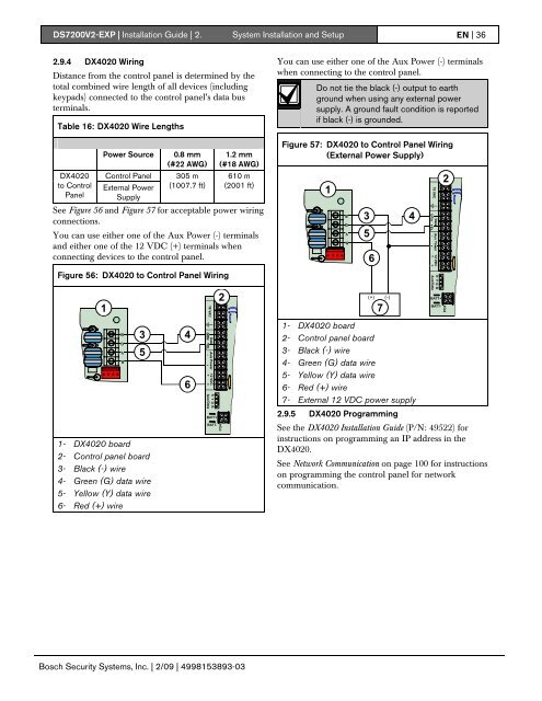
<strong>DS7200V2</strong>-<strong>EXP</strong> | Installation Guide | 2. System Installation and Setup EN | 362.9.4 DX4020 WiringDistance from the control panel is determined by thetotal combined wire length of all devices (includingkeypads) connected to the control panel’s data busterminals.Table 16: DX4020 Wire LengthsDX4020to ControlPanelPower SourceControl PanelExternal PowerSupply0.8 mm(#22 AWG)305 m(1007.7 ft)1.2 mm(#18 AWG)610 m(2001 ft)See Figure 56 and Figure 57 for acceptable power wiringconnections.You can use either one of the Aux Power (-) terminalsand either one of the 12 VDC (+) terminals whenconnecting devices to the control panel.You can use either one of the Aux Power (-) terminalswhen connecting to the control panel.Do not tie the black (-) output to earthground when using any external powersupply. A ground fault condition is reportedif black (-) is grounded.Figure 57: DX4020 to Control Panel Wiring(External Power Supply)135642Figure 56: DX4020 to Control Panel Wiring12(+) (-)7BATT+BATT-35461- DX4020 board2- Control panel board3- Black (-) wire4- Green (G) data wire5- Yellow (Y) data wire6- Red (+) wire7- External 12 VDC power supplyBATT+2.9.5 DX4020 Programming1- DX4020 board2- Control panel board3- Black (-) wire4- Green (G) data wire5- Yellow (Y) data wire6- Red (+) wireBATT-See the DX4020 Installation Guide (P/N: 49522) forinstructions on programming an IP address in theDX4020.See Network Communication on page 100 for instructionson programming the control panel for networkcommunication.Bosch Security Systems, Inc. | 2/09 | 4998153893-03