DS7200V2-EXP - Simon Technologies
DS7200V2-EXP - Simon Technologies
DS7200V2-EXP - Simon Technologies

Create successful ePaper yourself
Turn your PDF publications into a flip-book with our unique Google optimized e-Paper software.
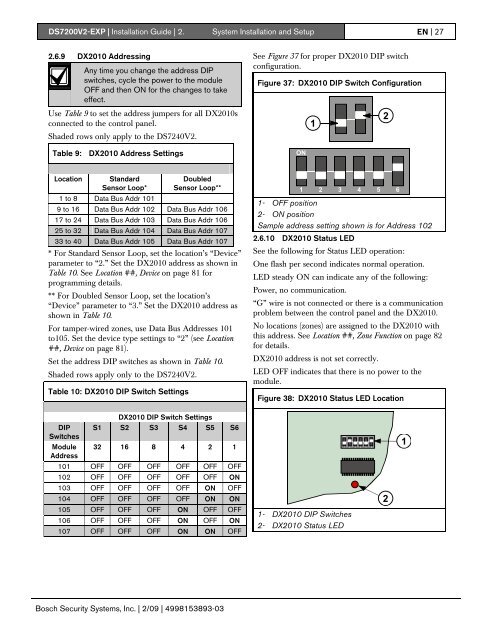
<strong>DS7200V2</strong>-<strong>EXP</strong> | Installation Guide | 2. System Installation and Setup EN | 272.6.9 DX2010 AddressingAny time you change the address DIPswitches, cycle the power to the moduleOFF and then ON for the changes to takeeffect.See Figure 37 for proper DX2010 DIP switchconfiguration.Figure 37: DX2010 DIP Switch ConfigurationUse Table 9 to set the address jumpers for all DX2010sconnected to the control panel.Shaded rows only apply to the DS7240V2.12Table 9: DX2010 Address SettingsONLocation StandardSensor Loop*1 to 8 Data Bus Addr 101DoubledSensor Loop**9 to 16 Data Bus Addr 102 Data Bus Addr 10617 to 24 Data Bus Addr 103 Data Bus Addr 10625 to 32 Data Bus Addr 104 Data Bus Addr 10733 to 40 Data Bus Addr 105 Data Bus Addr 107* For Standard Sensor Loop, set the location’s “Device”parameter to “2.” Set the DX2010 address as shown inTable 10. See Location ##, Device on page 81 forprogramming details.** For Doubled Sensor Loop, set the location’s“Device” parameter to “3.” Set the DX2010 address asshown in Table 10.For tamper-wired zones, use Data Bus Addresses 101to105. Set the device type settings to “2” (see Location##, Device on page 81).Set the address DIP switches as shown in Table 10.Shaded rows apply only to the DS7240V2.Table 10: DX2010 DIP Switch Settings1 2 3 4 5 61- OFF position2- ON positionSample address setting shown is for Address 1022.6.10 DX2010 Status LEDSee the following for Status LED operation:One flash per second indicates normal operation.LED steady ON can indicate any of the following:Power, no communication.“G” wire is not connected or there is a communicationproblem between the control panel and the DX2010.No locations (zones) are assigned to the DX2010 withthis address. See Location ##, Zone Function on page 82for details.DX2010 address is not set correctly.LED OFF indicates that there is no power to themodule.Figure 38: DX2010 Status LED LocationDX2010 DIP Switch SettingsDIPSwitchesModuleAddressS1 S2 S3 S4 S5 S632 16 8 4 2 1ON1 2 3 4 5 61101 OFF OFF OFF OFF OFF OFF102 OFF OFF OFF OFF OFF ON103 OFF OFF OFF OFF ON OFF104 OFF OFF OFF OFF ON ON2105 OFF OFF OFF ON OFF OFF106 OFF OFF OFF ON OFF ON107 OFF OFF OFF ON ON OFF1- DX2010 DIP Switches2- DX2010 Status LEDBosch Security Systems, Inc. | 2/09 | 4998153893-03