DS7200V2-EXP - Simon Technologies
DS7200V2-EXP - Simon Technologies
DS7200V2-EXP - Simon Technologies

Create successful ePaper yourself
Turn your PDF publications into a flip-book with our unique Google optimized e-Paper software.
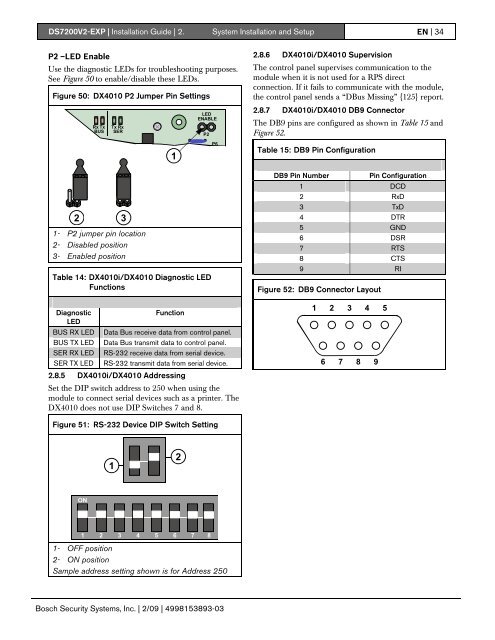
<strong>DS7200V2</strong>-<strong>EXP</strong> | Installation Guide | 2. System Installation and Setup EN | 34P2 –LED EnableUse the diagnostic LEDs for troubleshooting purposes.See Figure 50 to enable/disable these LEDs.Figure 50: DX4010 P2 Jumper Pin Settings2.8.6 DX4010i/DX4010 SupervisionThe control panel supervises communication to themodule when it is not used for a RPS directconnection. If it fails to communicate with the module,the control panel sends a “DBus Missing” {125} report.Rx TxBUSTxSER RxLEDENABLEP22.8.7 DX4010i/DX4010 DB9 ConnectorThe DB9 pins are configured as shown in Table 15 andFigure 52.1P6Table 15: DB9 Pin Configuration2 31- P2 jumper pin location2- Disabled position3- Enabled positionTable 14: DX4010i/DX4010 Diagnostic LEDFunctionsDB9 Pin NumberPin Configuration1 DCD2 RxD3 TxD4 DTR5 GND6 DSR7 RTS8 CTS9 RIFigure 52: DB9 Connector LayoutDiagnosticLEDBUS RX LEDBUS TX LEDSER RX LEDSER TX LEDFunctionData Bus receive data from control panel.Data Bus transmit data to control panel.RS-232 receive data from serial device.RS-232 transmit data from serial device.2.8.5 DX4010i/DX4010 AddressingSet the DIP switch address to 250 when using themodule to connect serial devices such as a printer. TheDX4010 does not use DIP Switches 7 and 8.1 2 3 4 56 7 8 9Figure 51: RS-232 Device DIP Switch Setting12ON1 2 3 4 5 6 7 81- OFF position2- ON positionSample address setting shown is for Address 250Bosch Security Systems, Inc. | 2/09 | 4998153893-03