DS7200V2-EXP - Simon Technologies
DS7200V2-EXP - Simon Technologies
DS7200V2-EXP - Simon Technologies

Create successful ePaper yourself
Turn your PDF publications into a flip-book with our unique Google optimized e-Paper software.
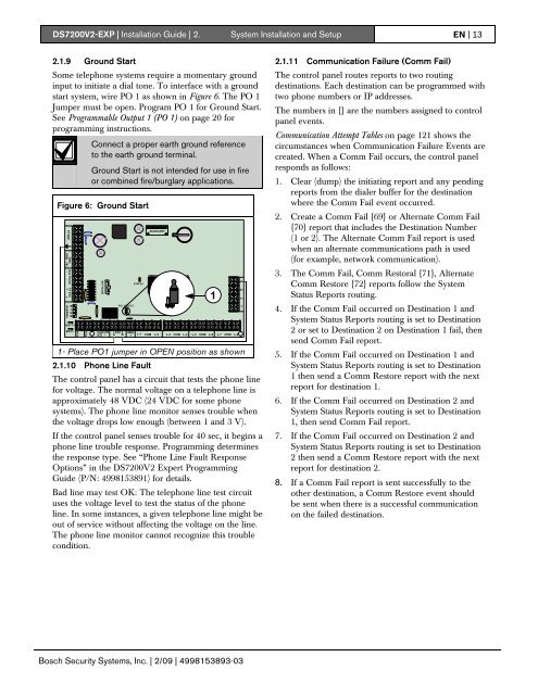
<strong>DS7200V2</strong>-<strong>EXP</strong> | Installation Guide | 2. System Installation and Setup EN | 132.1.9 Ground StartSome telephone systems require a momentary groundinput to initiate a dial tone. To interface with a groundstart system, wire PO 1 as shown in Figure 6. The PO 1Jumper must be open. Program PO 1 for Ground Start.See Programmable Output 1 (PO 1) on page 20 forprogramming instructions.Connect a proper earth ground referenceto the earth ground terminal.Ground Start is not intended for use in fireor combined fire/burglary applications.Figure 6: Ground StartBATT+BATT-ALRM+PO1A BPO1 SELECTSTATUSAUXILIARY1TSMK+L-1 COM L-2 L-3 COM L-4 L-5 COM L-6 L-7 COM L-81- Place PO1 jumper in OPEN position as shown2.1.10 Phone Line FaultThe control panel has a circuit that tests the phone linefor voltage. The normal voltage on a telephone line isapproximately 48 VDC (24 VDC for some phonesystems). The phone line monitor senses trouble whenthe voltage drops low enough (between 1 and 3 V).If the control panel senses trouble for 40 sec, it begins aphone line trouble response. Programming determinesthe response type. See “Phone Line Fault ResponseOptions” in the <strong>DS7200V2</strong> Expert ProgrammingGuide (P/N: 4998153891) for details.Bad line may test OK: The telephone line test circuituses the voltage level to test the status of the phoneline. In some instances, a given telephone line might beout of service without affecting the voltage on the line.The phone line monitor cannot recognize this troublecondition.RR1T12.1.11 Communication Failure (Comm Fail)The control panel routes reports to two routingdestinations. Each destination can be programmed withtwo phone numbers or IP addresses.The numbers in {} are the numbers assigned to controlpanel events.Communication Attempt Tables on page 121 shows thecircumstances when Communication Failure Events arecreated. When a Comm Fail occurs, the control panelresponds as follows:1. Clear (dump) the initiating report and any pendingreports from the dialer buffer for the destinationwhere the Comm Fail event occurred.2. Create a Comm Fail {69} or Alternate Comm Fail{70} report that includes the Destination Number(1 or 2). The Alternate Comm Fail report is usedwhen an alternate communications path is used(for example, network communication).3. The Comm Fail, Comm Restoral {71}, AlternateComm Restore {72} reports follow the SystemStatus Reports routing.4. If the Comm Fail occurred on Destination 1 andSystem Status Reports routing is set to Destination2 or set to Destination 2 on Destination 1 fail, thensend Comm Fail report.5. If the Comm Fail occurred on Destination 1 andSystem Status Reports routing is set to Destination1 then send a Comm Restore report with the nextreport for destination 1.6. If the Comm Fail occurred on Destination 2 andSystem Status Reports routing is set to Destination1, then send Comm Fail report.7. If the Comm Fail occurred on Destination 2 andSystem Status Reports routing is set to Destination2 then send a Comm Restore report with the nextreport for destination 2.8. If a Comm Fail report is sent successfully to theother destination, a Comm Restore event shouldbe sent when there is a successful communicationon the failed destination.Bosch Security Systems, Inc. | 2/09 | 4998153893-03