DS7200V2-EXP - Simon Technologies
DS7200V2-EXP - Simon Technologies
DS7200V2-EXP - Simon Technologies

Create successful ePaper yourself
Turn your PDF publications into a flip-book with our unique Google optimized e-Paper software.
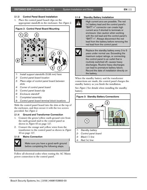
<strong>DS7200V2</strong>-<strong>EXP</strong> | Installation Guide | 2. System Installation and Setup EN | 112.1.3 Control Panel Board Installation1. Place the control panel board clips on theappropriate standoffs in the enclosure. See Figure 2.Figure 2: Control Panel Board Mounting1 232.1.6 Standby Battery InstallationHigh current arcs are possible. The red(+) battery lead and the control panel’s“BATT +” connector can create highcurrent arcs if shorted to terminals orenclosure. Use caution when workingwith the red lead and the control panel’s“BATT +”. Always disconnect the redlead from the battery before removing thered lead from the control panel.81- Install support standoffs (0.08 mm) here2- Control panel board location3- Place edge of control panel board betweenslots4- Corner of control panel board5- Control panel board clip6- Enclosure standoff7- Completed assembly8- Control panel board terminal block locationsSlide the control panel board into the slots at the top ofthe enclosure, and then secure it with the two screwsprovided. See Figure 2.2.1.4 Ground and Transformer Connection1. Connect the green/yellow earth ground wire fromthe earth ground stud to the control panel asshown in Figure 65 on page 127.2. Connect the orange and yellow wires from thetransformer to the control panel as shown in Figure65 on page 127.2.1.5 Mains ConnectionMake sure you have a good earth groundbefore completing the following steps.4567=Replace the standby battery every 3 to 5years under normal use. Exceeding themaximum output ratings, or connectingthe control panel to an outlet that isroutinely switched off, causes heavydischarges. Routine heavy dischargescan lead to premature battery failure.Record the date of installation directly onthe battery.When the standby battery and the transformerconnections are made, the control panel charges thestandby battery as you finish the installation.See Figure 3 for details when installing the standbybattery.Figure 3: Standby Battery Connections14(-)(+)1- Standby battery2- Control panel board3- Black (-) line4- Red (+) line3BATT+BATT-2Follow all electrical codes when routing the AC Mainspower connection to the control panel.Bosch Security Systems, Inc. | 2/09 | 4998153893-03