DS7200V2-EXP - Simon Technologies
DS7200V2-EXP - Simon Technologies
DS7200V2-EXP - Simon Technologies

Create successful ePaper yourself
Turn your PDF publications into a flip-book with our unique Google optimized e-Paper software.
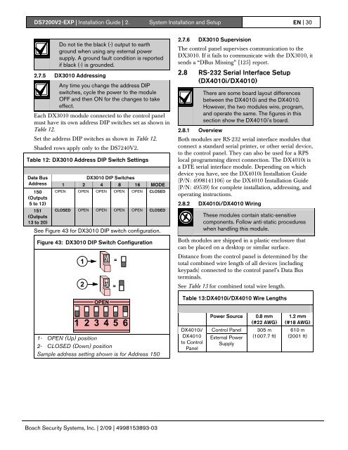
<strong>DS7200V2</strong>-<strong>EXP</strong> | Installation Guide | 2. System Installation and Setup EN | 30Do not tie the black (-) output to earthground when using any external powersupply. A ground fault condition is reportedif black (-) is grounded.2.7.5 DX3010 AddressingAny time you change the address DIPswitches, cycle the power to the moduleOFF and then ON for the changes to takeeffect.Each DX3010 module connected to the control panelmust have its own address DIP switches set as shown inTable 12.Set the address DIP switches as shown in Table 12.Shaded rows apply only to the DS7240V2.Table 12: DX3010 Address DIP Switch SettingsData BusDX3010 DIP SwitchesAddress 1 2 4 8 16 MODE150 OPEN OPEN OPEN OPEN OPEN CLOSED(Outputs5 to 12)151(Outputs13 to 20)CLOSED OPEN OPEN OPEN OPEN CLOSEDSee Figure 43 for DX3010 DIP switch configuration.Figure 43: DX3010 DIP Switch Configuration12OPEN==2.7.6 DX3010 SupervisionThe control panel supervises communication to theDX3010. If it fails to communicate with the DX3010, itsends a “DBus Missing” {125} report.2.8 RS-232 Serial Interface Setup(DX4010i/DX4010)There are some board layout differencesbetween the DX4010i and the DX4010.However, the two modules wire, program,and operate the same. The figures in thissection show the DX4010i’s board.2.8.1 OverviewBoth modules are RS-232 serial interface modules thatconnect a standard serial printer, or other serial device,to the control panel. They can also be used for a RPSlocal programming direct connection. The DX4010i isa DTE serial interface module. Depending on whichdevice you have, see the DX4010i Installation Guide(P/N: 4998141106) or the DX4010 Installation Guide(P/N: 49539) for complete installation, addressing, andoperating instructions.2.8.2 DX4010i/DX4010 WiringThese modules contain static-sensitivecomponents. Follow anti-static procedureswhen handling this module.Both modules are shipped in a plastic enclosure thatcan be placed on a desktop or similar surface.Distance from the control panel is determined by thetotal combined wire length of all devices (includingkeypads) connected to the control panel’s Data Busterminals.See Table 13 for combined total wire length.Table 13: DX4010i/DX4010 Wire Lengths1 2 3 4 5 61- OPEN (Up) position2- CLOSED (Down) positionSample address setting shown is for Address 150DX4010i/DX4010to ControlPanelPower SourceControl PanelExternal PowerSupply0.8 mm(#22 AWG)305 m(1007.7 ft)1.2 mm(#18 AWG)610 m(2001 ft)Bosch Security Systems, Inc. | 2/09 | 4998153893-03