DS7200V2-EXP - Simon Technologies
DS7200V2-EXP - Simon Technologies
DS7200V2-EXP - Simon Technologies

Create successful ePaper yourself
Turn your PDF publications into a flip-book with our unique Google optimized e-Paper software.
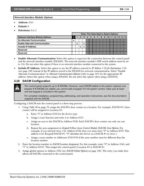
<strong>DS7200V2</strong>-<strong>EXP</strong> | Installation Guide | 3. Control Panel Programming EN | 104Network Interface Module Options• Address: 3541• Default: 0• Selections: 0 to 3Enter This Data Digit to Select OptionsNetwork Interface Module Options 0 1 2 3 4 5 6 7 8 9 10 11 12 13 14 15No Alternate Communication •Enable Alternate Communication • •Include IP Address • •ReservedReserved• Enable Alternate Communication: Select this option to supervise the connection between the control paneland the network interface module (DX4020). The network interface module’s DIP switch address must be setto 134. Do not select this option if there is no network interface module connected to the system.• Include IP Address: Select this option to use the IP address entered in IP Address 1 (2) for Destination 1 (2)(see page 100) instead of the IP address stored in the DX4020 for network communication. Select “EnableAlternate Communication” in Alternate Communication Options (refer to page 101) for the appropriate IPaddress. Select this option when using a DX4020. Do not select this option when using a DX4010i.3.10 DACM ConfigurationThe control panel supports up to 8 DACMs. However, each DACM added to the system replaces onekeypad. If 8 DACMs are added, you cannot add a keypad. For full system control, make sure at leastone text keypad is included in the system.For complete installation, programming, addressing, and operation instructions, see the documentationsupplied with the DACM.Configuring a DACM into the control panel is a three-step process:1. Using Table 30 on page 79, assign the DACM’s door contact as a location. For example, DACM #1’s doorcontact will be assigned to Location #5.a. Enter “6” at Address 0726 for the device type.b. Assign a zone function and enter it in Address 0727.c. Assign an area to the DACM in Address 0728. Each DACM’s door contact can only use onelocation.d. Repeat the area assignment in Keypad #/Door Access Control Module (DACM) Area Options. Forexample, if you selected Area 1 for Address 0728, then you must enter “9” in Address 0679. Thisaddress is for Keypad/DACM #1. “9” identifies the device as a DACM #1 in Area 1.e. Assign a zone number in Addresses 0729-0730 if the zone number must be different than thelocation number.2. Enter the location number in DACM Location Assignment. For this example, enter “0” in Address 3546, and“5” in Address 03547. This assigns the control panel’s Location #5 to DACM #1.3. Assign global options in Address 3562 (see DACM Global Options on page 106). The entry you make hereaffects all DACMs connected to the control panel.Bosch Security Systems, Inc. | 2/09 | 4998153893-03