DS7200V2-EXP - Simon Technologies
DS7200V2-EXP - Simon Technologies
DS7200V2-EXP - Simon Technologies

Create successful ePaper yourself
Turn your PDF publications into a flip-book with our unique Google optimized e-Paper software.
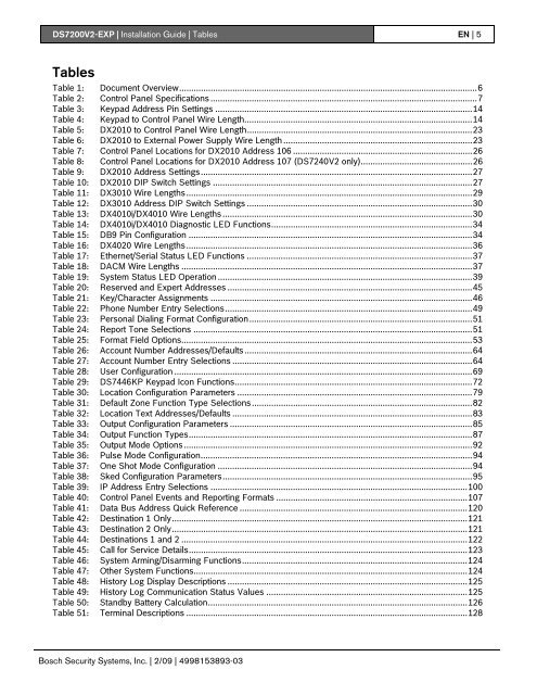
<strong>DS7200V2</strong>-<strong>EXP</strong> | Installation Guide | Tables EN | 5TablesTable 1: Document Overview...........................................................................................................................6Table 2: Control Panel Specifications ..............................................................................................................7Table 3: Keypad Address Pin Settings ..........................................................................................................14Table 4: Keypad to Control Panel Wire Length..............................................................................................14Table 5: DX2010 to Control Panel Wire Length.............................................................................................23Table 6: DX2010 to External Power Supply Wire Length ..............................................................................23Table 7: Control Panel Locations for DX2010 Address 106 ..........................................................................26Table 8: Control Panel Locations for DX2010 Address 107 (DS7240V2 only)..............................................26Table 9: DX2010 Address Settings................................................................................................................27Table 10: DX2010 DIP Switch Settings ...........................................................................................................27Table 11: DX3010 Wire Lengths......................................................................................................................29Table 12: DX3010 Address DIP Switch Settings .............................................................................................30Table 13: DX4010i/DX4010 Wire Lengths .......................................................................................................30Table 14: DX4010i/DX4010 Diagnostic LED Functions...................................................................................34Table 15: DB9 Pin Configuration .....................................................................................................................34Table 16: DX4020 Wire Lengths......................................................................................................................36Table 17: Ethernet/Serial Status LED Functions .............................................................................................37Table 18: DACM Wire Lengths ........................................................................................................................37Table 19: System Status LED Operation .........................................................................................................39Table 20: Reserved and Expert Addresses .....................................................................................................45Table 21: Key/Character Assignments ............................................................................................................46Table 22: Phone Number Entry Selections......................................................................................................49Table 23: Personal Dialing Format Configuration............................................................................................51Table 24: Report Tone Selections ...................................................................................................................51Table 25: Format Field Options........................................................................................................................53Table 26: Account Number Addresses/Defaults..............................................................................................64Table 27: Account Number Entry Selections ...................................................................................................64Table 28: User Configuration ...........................................................................................................................69Table 29: DS7446KP Keypad Icon Functions..................................................................................................72Table 30: Location Configuration Parameters .................................................................................................79Table 31: Default Zone Function Type Selections...........................................................................................82Table 32: Location Text Addresses/Defaults ...................................................................................................83Table 33: Output Configuration Parameters ....................................................................................................85Table 34: Output Function Types.....................................................................................................................87Table 35: Output Mode Options.......................................................................................................................92Table 36: Pulse Mode Configuration................................................................................................................94Table 37: One Shot Mode Configuration .........................................................................................................94Table 38: Sked Configuration Parameters.......................................................................................................95Table 39: IP Address Entry Selections ..........................................................................................................100Table 40: Control Panel Events and Reporting Formats ...............................................................................107Table 41: Data Bus Address Quick Reference ..............................................................................................120Table 42: Destination 1 Only..........................................................................................................................121Table 43: Destination 2 Only..........................................................................................................................121Table 44: Destinations 1 and 2 ......................................................................................................................122Table 45: Call for Service Details...................................................................................................................123Table 46: System Arming/Disarming Functions.............................................................................................124Table 47: Other System Functions.................................................................................................................124Table 48: History Log Display Descriptions ...................................................................................................125Table 49: History Log Communication Status Values ...................................................................................125Table 50: Standby Battery Calculation...........................................................................................................126Table 51: Terminal Descriptions ....................................................................................................................128Bosch Security Systems, Inc. | 2/09 | 4998153893-03