DS7200V2-EXP - Simon Technologies
DS7200V2-EXP - Simon Technologies
DS7200V2-EXP - Simon Technologies

You also want an ePaper? Increase the reach of your titles
YUMPU automatically turns print PDFs into web optimized ePapers that Google loves.
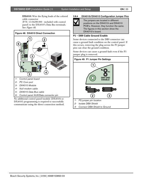
<strong>DS7200V2</strong>-<strong>EXP</strong> | Installation Guide | 2. System Installation and Setup EN | 33DX4010: Wire the flying leads of the coloredcable connector(P/N: 15-04298-000 - included with controlpanel) to the DX4010’s Data Bus terminals.See Figure 48.Figure 48: DX4010 Direct Connection6BATT+BATT-1 23Serial Port2.8.4 DX4010i/DX4010 Configuration Jumper PinsThe jumpers are located in differentpositions on the DX4010i and DX4010PCB’s. However, they function the same.The figures in this section show theDX4010i’s board.P1 – DB9 Cable Ground EnableSome devices connected to the DB9 connector cancause a ground fault condition on the control panel. Ifthis occurs, removing the plug across the P3 jumperpins can clear the ground condition.Some devices can cause a ground fault even if the P3jumper plug is removed.Figure 49: P1 Jumper Pin Settings1451- Control panel board2- PC Com port3- DX4010 Module4- Null modem cable5- DX4010 Data Bus cable6- Control panel AUX/Data connector pinNo additional control panel/module (DX4010i orDX4010) programming is required to successfullycommunicate using the direct connection method.P1DB9 GNDENABLE2 31- P3 jumper pin location2- Isolate DB9 Shield3- Connect DB9 Shield to GroundBosch Security Systems, Inc. | 2/09 | 4998153893-03