<strong>DS7200V2</strong>-<strong>EXP</strong> | Installation Guide | 2. System Installation and Setup EN | 42Testing RF DevicesPress [2] from the RF Menu to test RF devices thathave been added to the system. The display shows thefollowing:LocationAreaLoc9 A1 Zn9Test? Press 9*.The display scrolls through all properly configureddevices (the display above shows Location 9 as anexample) and asks if you wish to test. Using Location 9as an example, press [9] followed by [*] to test the RFdevice at Location 9. The first line of the display shows“Activate device!”, indicating that the device must beactivated in order to test it. Once the device isactivated, the following display appears:L03 M01 P08Loc9 A1 Zn9ZoneNumberThe first line in the display above shows the RFdevice’s test status:• L03: System recognizes the device and that thedevice is operating properly. Other status displaysinclude:- L02: System recognizes the device and that thedevice operation is fair.- L01: The device must be relocated to allow forproper operation.• M01: Counts the number of device activations. Forexample, an RF3401E Point Transmitter is thedevice being tested. When the magnetic assemblyis removed from the point transmitter base, theactivation counter counts one activation. When themagnetic assembly is returned to the zonetransmitter base, the counter counts a secondactivation. Opening and closing the zonetransmitter’s case are also considered activations.• P08: Message packet transmission.- Fault, RF Keyfob Panic, RF Keypad Panic, andRestoral messages are transmitted with 8packets.- Supervisory and Test transmissions (smokedetectors) consist of 4 packets.- RF keypads send 4 packets for all keys exceptthe Emergency keys, which transmit 8 packets.- RF key fobs send 4 packets for normaloperation and 8 packets for the Panic button(Arm and Disarm pressed simultaneously).RF receivers need to receive 7 or 8 data packets from atransmitter in order for that transmitter to beconsidered “Good.” When testing RF keypads or keyfobs, the panic functions must be used, otherwise theunits only send 4 packets (see packet count above).When testing the installation of a smoke unit, the testbutton should not be used. Doing so results in a 4-packet transmission. Instead, tamper the unit or cause itto alarm (use canned smoke).When you have finished testing a device, press [#]. Thelist of RF devices scrolls beginning with the first(lowest) location assigned to a RF device. Selectanother location to test by entering the locationnumber followed by the [*] and repeating theprocedure described above. If you are finished testing,press [#] again to return to the RF Menu.View/Remove RF ID CodesPress [3] from the RF Menu to view or remove RF IDcodes that were added to the system. The display thenscrolls through the properly configured RF devices:ZoneLocation AreaNumberLoc9 A1 Zn9ID = XXXXXXXXXID Code (see back of device)After each ID code is shown, the display toggles to thefollowing message before moving to the next ID code:“To remove ID press 9* (the number “9” represents thelocation number and is used as an example).To remove the ID code, press the number key(s) thatcorresponds with the location number (for thisexample, press [9]). Then press [*]. Press theappropriate number key(s) followed by [*]. The displaythen shows “Removed ID” on the first line with thelocation, area and zone numbers of the removed ID onthe second line.To remove additional ID codes, press [#]. The scrollinglist of RF devices returns. Press [#] again to return tothe RF Menu when you have finished removing IDcodes. Pressing [#] a third time returns you to theInstaller Menu.Bosch Security Systems, Inc. | 2/09 | 4998153893-03
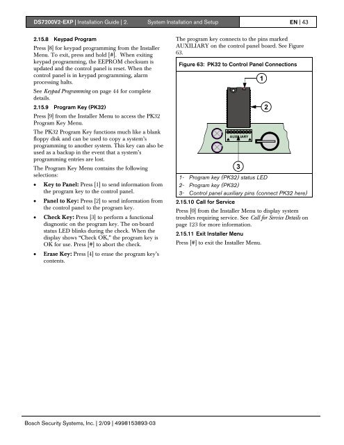
<strong>DS7200V2</strong>-<strong>EXP</strong> | Installation Guide | 2. System Installation and Setup EN | 432.15.8 Keypad ProgramPress [8] for keypad programming from the InstallerMenu. To exit, press and hold [#]. When exitingkeypad programming, the EEPROM checksum isupdated and the control panel is reset. When thecontrol panel is in keypad programming, alarmprocessing halts.See Keypad Programming on page 44 for completedetails.2.15.9 Program Key (PK32)Press [9] from the Installer Menu to access the PK32Program Key Menu.The PK32 Program Key functions much like a blankfloppy disk and can be used to copy a system’sprogramming to another system. This key can also beused as a backup in the event that a system’sprogramming entries are lost.The Program Key Menu contains the followingselections:• Key to Panel: Press [1] to send information fromthe program key to the control panel.• Panel to Key: Press [2] to send information fromthe control panel to the program key.• Check Key: Press [3] to perform a functionaldiagnostic on the program key. The on-boardstatus LED blinks during the check. When thedisplay shows “Check OK,” the program key isOK for use. Press [#] to abort the check.• Erase Key: Press [4] to erase the program key’scontents.The program key connects to the pins markedAUXILIARY on the control panel board. See Figure63.Figure 63: PK32 to Control Panel ConnectionsAUXILIARY31- Program key (PK32) status LED2- Program key (PK32)3- Control panel auxiliary pins (connect PK32 here)2.15.10 Call for ServicePress [0] from the Installer Menu to display systemtroubles requiring service. See Call for Service Details onpage 123 for more information.2.15.11 Exit Installer MenuPress [#] to exit the Installer Menu.12Bosch Security Systems, Inc. | 2/09 | 4998153893-03