DS7200V2-EXP - Simon Technologies
DS7200V2-EXP - Simon Technologies
DS7200V2-EXP - Simon Technologies

Create successful ePaper yourself
Turn your PDF publications into a flip-book with our unique Google optimized e-Paper software.
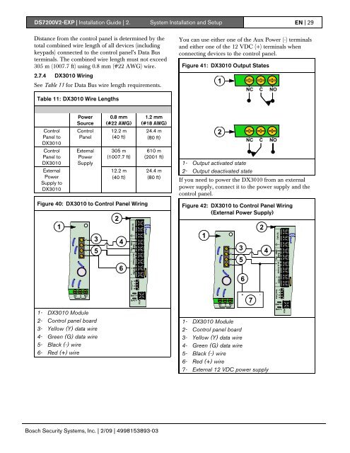
<strong>DS7200V2</strong>-<strong>EXP</strong> | Installation Guide | 2. System Installation and Setup EN | 29Distance from the control panel is determined by thetotal combined wire length of all devices (includingkeypads) connected to the control panel’s Data Busterminals. The combined wire length must not exceed305 m (1007.7 ft) using 0.8 mm (#22 AWG) wire.You can use either one of the Aux Power (-) terminalsand either one of the 12 VDC (+) terminals whenconnecting devices to the control panel.Figure 41: DX3010 Output States2.7.4 DX3010 WiringSee Table 11 for Data Bus wire length requirements.1NCCNOTable 11: DX3010 Wire LengthsPowerSource0.8 mm(#22 AWG)1.2 mm(#18 AWG)ControlPanel toDX3010ControlPanel12.2 m(40 ft)24.4 m(80 ft)2NCCNOControlPanel toDX3010ExternalPowerSupply toDX3010ExternalPowerSupply305 m(1007.7 ft)12.2 m(40 ft)610 m(2001 ft)24.4 m(80 ft)1- Output activated state2- Output deactivated stateIf you need to power the DX3010 from an externalpower supply, connect it to the power supply and thecontrol panel.Figure 40: DX3010 to Control Panel Wiring1YGBR23 456Figure 42: DX3010 to Control Panel Wiring(External Power Supply)1YGBR35624NCC8NOBATT+BATT-NCC8NO+ -7BATT+1- DX3010 Module2- Control panel board3- Yellow (Y) data wire4- Green (G) data wire5- Black (-) wire6- Red (+) wire1- DX3010 Module2- Control panel board3- Yellow (Y) data wire4- Green (G) data wire5- Black (-) wire6- Red (+) wire7- External 12 VDC power supplyBATT-Bosch Security Systems, Inc. | 2/09 | 4998153893-03