DS7200V2-EXP - Simon Technologies
DS7200V2-EXP - Simon Technologies
DS7200V2-EXP - Simon Technologies

You also want an ePaper? Increase the reach of your titles
YUMPU automatically turns print PDFs into web optimized ePapers that Google loves.
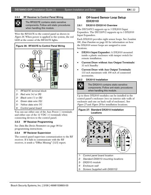
<strong>DS7200V2</strong>-<strong>EXP</strong> | Installation Guide | 2. System Installation and Setup EN | 222.5.2 RF Receiver to Control Panel WiringThe RF3227E contains static-sensitivecomponents. Follow anti-static procedureswhen handling this module.Wire the RF3227E to the control panel as shown inFigure 26. When power is applied to the system, the redLED at the center of the RF3227E lights.Figure 26: RF3227E to Control Panel Wiring1RBGY2 3451- RF3227E terminal block2- Red wire (+) or (R)3- Black wire (-) or (B)4- Green data wire (G)5- Yellow data wire (Y)6- Control panel boardBATT+BATT-You can use either one of the Aux Power (-) terminalsand either one of the 12 VDC (+) terminals whenconnecting devices to the control panel.2.5.3 RF Receiver ProgrammingSee Data Bus Device Parameters on page 98 forprogramming instructions.2.5.4 RF Reciever SupervisionThe control panel supervises communication to the RFreceiver. If it fails to communicate with the RFreceiver, it sends a “DBus Missing” {125} report.62.6 Off-board Sensor Loop Setup(DX2010)2.6.1 DX2010 (DX2014) OverviewThe DS7240V2 supports up to 5 DX2010 InputExpanders. The DS7220V2 supports up to 3 DX2010Input Expanders.Each DX2010 provides eight sensor loops. See Location##, Zone Function on page 82 for information on howthe DX2010 sensor loops are assigned to zonelocations.• DX2014 Input Expander: A DX2010 mountedinside a plastic enclosure with tamper switch forremote installation.• Current Draw without Aux Output Terminals:35 mA Standby• Current Draw with Aux Output Terminals:135 mA maximum with 100 mA of connectedaccessories.2.6.2 DX2010 InstallationThe DX2010 contains static-sensitivecomponents. Follow anti-static procedureswhen handling this module.Up to three DX2010 modules can be installed in thecontrol panel’s enclosure (two on interior side walls ofenclosure and one on back wall of enclosure). SeeFigure 27 and Figure 28 for installation locations.Figure 27: Standard DX2010 InstallationLocations213451- Control panel board location2- Standard DX2010 mounting locations3- DX2010 module4- Enclosure wall5- Screws (supplied with DX2010)Bosch Security Systems, Inc. | 2/09 | 4998153893-03