DS7200V2-EXP - Simon Technologies
DS7200V2-EXP - Simon Technologies
DS7200V2-EXP - Simon Technologies

You also want an ePaper? Increase the reach of your titles
YUMPU automatically turns print PDFs into web optimized ePapers that Google loves.
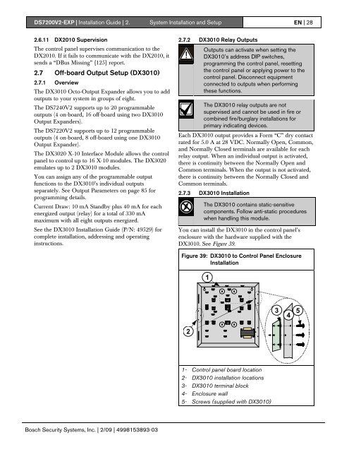
<strong>DS7200V2</strong>-<strong>EXP</strong> | Installation Guide | 2. System Installation and Setup EN | 282.6.11 DX2010 SupervisionThe control panel supervises communication to theDX2010. If it fails to communicate with the DX2010, itsends a “DBus Missing” {125} report.2.7 Off-board Output Setup (DX3010)2.7.1 OverviewThe DX3010 Octo-Output Expander allows you to addoutputs to your system in groups of eight.The DS7240V2 supports up to 20 programmableoutputs (4 on-board, 16 off-board using two DX3010Output Expanders).The DS7220V2 supports up to 12 programmableoutputs (4 on-board, 8 off-board using one DX3010Output Expander).The DX3020 X-10 Interface Module allows the controlpanel to control up to 16 X-10 modules. The DX3020emulates up to 2 DX3010 modules.You can assign any of the programmable outputfunctions to the DX3010’s individual outputsseparately. See Output Parameters on page 85 forprogramming details.Current Draw: 10 mA Standby plus 40 mA for eachenergized output (relay) for a total of 330 mAmaximum with all eight outputs energized.See the DX3010 Installation Guide (P/N: 49529) forcomplete installation, addressing and operatinginstructions.2.7.2 DX3010 Relay OutputsOutputs can activate when setting theDX3010’s address DIP switches,programming the control panel, resettingthe control panel or applying power to thecontrol panel. Disconnect equipmentconnected to outputs when performingthese functions.The DX3010 relay outputs are notsupervised and cannot be used in fire orcombined fire/burglary installations forprimary indicating devices.Each DX3010 output provides a Form “C” dry contactrated for 5.0 A at 28 VDC. Normally Open, Common,and Normally Closed terminals are available for eachrelay output. When an individual output is activated,there is continuity between the Normally Open andCommon terminals. When the output is not activated,there is continuity between the Normally Closed andCommon terminals.2.7.3 DX3010 InstallationThe DX3010 contains static-sensitivecomponents. Follow anti-static procedureswhen handling this module.You can install the DX3010 in the control panel’senclosure with the hardware supplied with theDX3010. See Figure 39.Figure 39: DX3010 to Control Panel EnclosureInstallation134521- Control panel board location2- DX3010 installation locations3- DX3010 terminal block4- Enclosure wall5- Screws (supplied with DX3010)Bosch Security Systems, Inc. | 2/09 | 4998153893-03