DS7200V2-EXP - Simon Technologies
DS7200V2-EXP - Simon Technologies
DS7200V2-EXP - Simon Technologies

Create successful ePaper yourself
Turn your PDF publications into a flip-book with our unique Google optimized e-Paper software.
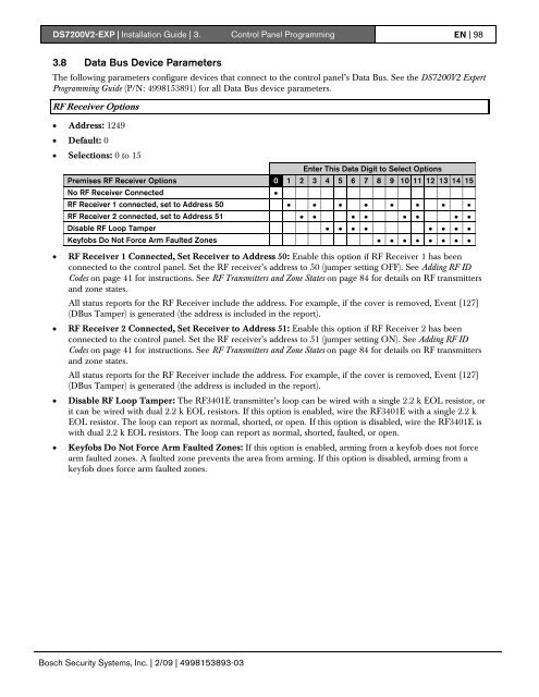
<strong>DS7200V2</strong>-<strong>EXP</strong> | Installation Guide | 3. Control Panel Programming EN | 983.8 Data Bus Device ParametersThe following parameters configure devices that connect to the control panel’s Data Bus. See the <strong>DS7200V2</strong> ExpertProgramming Guide (P/N: 4998153891) for all Data Bus device parameters.RF Receiver Options• Address: 1249• Default: 0• Selections: 0 to 15Enter This Data Digit to Select OptionsPremises RF Receiver Options 0 1 2 3 4 5 6 7 8 9 10 11 12 13 14 15No RF Receiver Connected •RF Receiver 1 connected, set to Address 50 • • • • • • • •RF Receiver 2 connected, set to Address 51 • • • • • • • •Disable RF Loop Tamper • • • • • • • •Keyfobs Do Not Force Arm Faulted Zones • • • • • • • •• RF Receiver 1 Connected, Set Receiver to Address 50: Enable this option if RF Receiver 1 has beenconnected to the control panel. Set the RF receiver’s address to 50 (jumper setting OFF). See Adding RF IDCodes on page 41 for instructions. See RF Transmitters and Zone States on page 84 for details on RF transmittersand zone states.All status reports for the RF Receiver include the address. For example, if the cover is removed, Event {127}(DBus Tamper) is generated (the address is included in the report).• RF Receiver 2 Connected, Set Receiver to Address 51: Enable this option if RF Receiver 2 has beenconnected to the control panel. Set the RF receiver’s address to 51 (jumper setting ON). See Adding RF IDCodes on page 41 for instructions. See RF Transmitters and Zone States on page 84 for details on RF transmittersand zone states.All status reports for the RF Receiver include the address. For example, if the cover is removed, Event {127}(DBus Tamper) is generated (the address is included in the report).• Disable RF Loop Tamper: The RF3401E transmitter’s loop can be wired with a single 2.2 k EOL resistor, orit can be wired with dual 2.2 k EOL resistors. If this option is enabled, wire the RF3401E with a single 2.2 kEOL resistor. The loop can report as normal, shorted, or open. If this option is disabled, wire the RF3401E iswith dual 2.2 k EOL resistors. The loop can report as normal, shorted, faulted, or open.• Keyfobs Do Not Force Arm Faulted Zones: If this option is enabled, arming from a keyfob does not forcearm faulted zones. A faulted zone prevents the area from arming. If this option is disabled, arming from akeyfob does force arm faulted zones.Bosch Security Systems, Inc. | 2/09 | 4998153893-03