

Adept Cobra s600/s800 Robot User's Guide - pulsar.com.tr
Adept Cobra s600/s800 Robot User's Guide - pulsar.com.tr
Adept Cobra s600/s800 Robot User's Guide - pulsar.com.tr

Create successful ePaper yourself
Turn your PDF publications into a flip-book with our unique Google optimized e-Paper software.
Using Digital I/O on <s<strong>tr</strong>ong>Robot</s<strong>tr</strong>ong> XIO Connector<br />
Optional I/O Products<br />
These optional products are also available for use with digital I/O:<br />
• XIO Breakout Cable, 5 meters long, with flying leads on user’s end. See page 60<br />
for information. This cable is not <s<strong>tr</strong>ong>com</s<strong>tr</strong>ong>patible with the XIO Termination Block<br />
mentioned below.<br />
• XIO Termination Block, with terminals for user wiring, plus input and output<br />
status LEDs. Connects to the XIO connector with 6 foot cable. See the <s<strong>tr</strong>ong>Adept</s<strong>tr</strong>ong> XIO<br />
Termination Block Installation <s<strong>tr</strong>ong>Guide</s<strong>tr</strong>ong> for details.<br />
XIO Input Signals<br />
The 12 input channels are arranged in two banks of six. Each bank is elec<strong>tr</strong>ically isolated<br />
from the other bank and is optically isolated from the robot’s ground. The six inputs<br />
within each bank share a <s<strong>tr</strong>ong>com</s<strong>tr</strong>ong>mon source/sink line.<br />
The inputs are accessed through direct connection to the XIO connector (see Table 5-5 on<br />
page 56), or through the optional XIO Termination Block. See the documentation supplied<br />
with the Termination Block for details.<br />
The XIO inputs cannot be used for REACTI programming, high-speed interrupts, or<br />
vision <strong>tr</strong>iggers. See the V+ Language User’s <s<strong>tr</strong>ong>Guide</s<strong>tr</strong>ong> for information on digital I/O<br />
programming.<br />
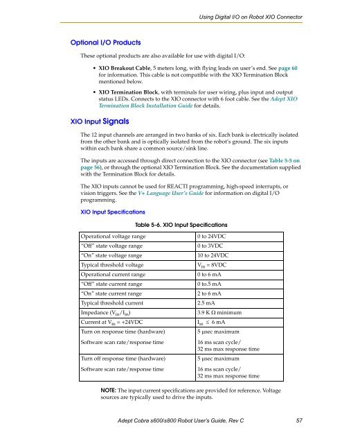
XIO Input Specifications<br />
Table 5-6. XIO Input Specifications<br />
Operational voltage range<br />
“Off” state voltage range<br />
“On” state voltage range<br />
Typical threshold voltage<br />
Operational current range<br />
“Off” state current range<br />
“On” state current range<br />
Typical threshold current<br />
Impedance (V in /I in )<br />
Current at V in = +24VDC<br />
Turn on response time (hardware)<br />
Software scan rate/response time<br />
Turn off response time (hardware)<br />
Software scan rate/response time<br />
0 to 24VDC<br />
0 to 3VDC<br />
10 to 24VDC<br />
V in = 8VDC<br />
0 to 6 mA<br />
0 to.5 mA<br />
2 to 6 mA<br />
2.5 mA<br />
3.9 K Ω minimum<br />
I in ≤ 6 mA<br />
5 µsec maximum<br />
16 ms scan cycle/<br />
32 ms max response time<br />
5 µsec maximum<br />
16 ms scan cycle/<br />
32 ms max response time<br />
NOTE: The input current specifications are provided for reference. Voltage<br />
sources are typically used to drive the inputs.<br />
<s<strong>tr</strong>ong>Adept</s<strong>tr</strong>ong> <s<strong>tr</strong>ong>Cobra</s<strong>tr</strong>ong> <s<strong>tr</strong>ong>s600</s<strong>tr</strong>ong>/<s<strong>tr</strong>ong>s800</s<strong>tr</strong>ong> <s<strong>tr</strong>ong>Robot</s<strong>tr</strong>ong> User’s <s<strong>tr</strong>ong>Guide</s<strong>tr</strong>ong>, Rev C 57


