- Page 2:
No part of this documentation may b
- Page 7 and 8:
8 Editing 110Editing in the Timelin
- Page 9 and 10:
11 Monitor 196Monitor ! Window 197S
- Page 11 and 12:
15 Strip and Bus Tools 275Strip and
- Page 14 and 15:
Ramses MSC 390Hardware Control Surf
- Page 16 and 17:
ADR 474Machines 474Macros 479Settin
- Page 18 and 19:
Internal Bussing & I/O Capabilities
- Page 20 and 21:
Thank you!Congratulations on your p
- Page 22 and 23:
• Full Delay Compensation (VS3 an
- Page 24 and 25:
Pyramix Virtual Studio OverviewPyra
- Page 26 and 27:
DSP(Mykerinos DSP Systems) or Core
- Page 28 and 29:
The default X-fade can be modified
- Page 30 and 31:
OverviewMassCore is an extremely po
- Page 32 and 33:
Core Load IndicatorsIn MassCore bas
- Page 34 and 35:
Note: These bars should be ignored
- Page 36 and 37:
OverviewEditing ProjectProjects are
- Page 38 and 39:
10. Click Next. The New Project Wiz
- Page 40 and 41:
HousekeepingAudition PlayMedia Fold
- Page 42 and 43:
N.B. In Pyramix User Libraries, the
- Page 44 and 45:
• A list of Pyramix Projects and/
- Page 46 and 47:
The left hand pane shows Libraries
- Page 48 and 49:
Library MenusThe Edit, View and Tri
- Page 50 and 51:
Consolidate(Libraries only) Opens t
- Page 52 and 53:
OptionsOpens the Library Settings d
- Page 54 and 55:
Quick ExportEnables Pyramix Master
- Page 56 and 57:
This module is initially aimed at p
- Page 58 and 59:
TimeZone Properties - BasicScaling
- Page 60 and 61:
When checked, the level of the high
- Page 62 and 63:
Managing Media FoldersChoose a medi
- Page 64 and 65:
The Mounting Rules dialog can be fo
- Page 66 and 67:
This will open a browser Window:Nav
- Page 68 and 69:
Using Offline/Reference LibrariesWh
- Page 70 and 71:
TracksAdding TracksEach Project has
- Page 72 and 73:
Other types of strip can be selecte
- Page 74 and 75:
Multiple tracksYou can also delete
- Page 76 and 77:
Record Ready - Recording commences
- Page 78 and 79:
Tracks Tab WindowThe Track Tab Wind
- Page 80 and 81:
If YES the automation envelope is d
- Page 82 and 83:
The rest of the fieldsAll the other
- Page 84 and 85:
Transport and Navigationwww.merging
- Page 86 and 87:
Clicking on the arrow opens a sub-m
- Page 88 and 89:
• Frames• Samples• [ms]• CD
- Page 90 and 91:
Bars & Beats Scale BarAs with the o
- Page 92 and 93:
value of 24.0 results in a Tempo of
- Page 94 and 95:
MarkersMarkers are shown in a Marke
- Page 96 and 97:
The slider varies the jog response
- Page 98 and 99:
Transport Control PanelPressing the
- Page 100 and 101:
The OverviewOverview Tab WindowThe
- Page 102 and 103:
Getting Audio into Pyramix Virtual
- Page 104 and 105:
Record Punch In (Auto)After Recordi
- Page 106 and 107:
3. Selecting Properties opens the S
- Page 108 and 109:
Manual DigitizingAutoconforming1. I
- Page 110 and 111:
Editingwww.merging.com/PyramixUSER
- Page 112 and 113:
Anatomy of a ClipMany Edit Commands
- Page 114 and 115:
Clip and Selection EditingMaster Cl
- Page 116 and 117:
Clips Rename open the Rename Clips
- Page 118 and 119:
TracksShows the tracks the media wa
- Page 120 and 121:
the Track on which you right-clicke
- Page 122 and 123:
Editing ModesThe current Editing Mo
- Page 124 and 125:
Tim Fade InTrim Fade In Symmetrical
- Page 126 and 127:
Delete and RippleCut and RipplePast
- Page 128 and 129:
Normalize Example:In this case with
- Page 130 and 131:
list shows information concerning t
- Page 132 and 133:
Source - Destination EditingConcept
- Page 134 and 135:
The menu item Edit > Source - Desti
- Page 136 and 137:
Fade Editorwww.merging.com/PyramixU
- Page 138 and 139:
Select/Edit Next FadeZoom around th
- Page 140 and 141:
• When the Force Safe box is chec
- Page 142 and 143:
Save X FadeThe dialog box opens wit
- Page 144 and 145:
Mixerwww.merging.com/PyramixUSER MA
- Page 146 and 147:
Configure PageMixer Configure PageI
- Page 148 and 149:
Strip and Bus operationsOnce select
- Page 150 and 151:
Effect ManagementClicking on Effect
- Page 152 and 153:
Right-clicking on an installed plug
- Page 154 and 155:
Wizard...Opens the Configuration Wi
- Page 156 and 157:
Mix !Basic MixerAutomatic Delay Com
- Page 158 and 159:
ColorsBus paths can be colored to a
- Page 160 and 161:
Mixer ComponentsInput StripsMixer I
- Page 162 and 163:
Multiple Mix Buses (Stems)Mono / St
- Page 164 and 165:
Channel Direct OutputsAll input str
- Page 166 and 167:
• Surround Center (Cs)By Default
- Page 168 and 169:
Aux Send RoutingWhen a Strip feedin
- Page 170 and 171:
Note: When IP:Off is displayed in t
- Page 172 and 173:
Stereo PannersPyramix offers a comp
- Page 174 and 175:
M&S Stereo StripsWhat is M&S?M&S st
- Page 176 and 177:
Checking the Connect automatically
- Page 178 and 179:
Delay CompensationDelay Compensatio
- Page 180 and 181:
When the Input Strip Mode is set to
- Page 182 and 183:
utton indicates that the effect is
- Page 184 and 185:
Ghost Effects and Plug-insEssential
- Page 186 and 187:
External InsertTo add an External I
- Page 188 and 189:
Show DistributionWhen checked, a na
- Page 190 and 191:
Saving / Loading Mixer PresetsMixer
- Page 192 and 193:
Level MeterToggles the main display
- Page 194 and 195:
Mixer Peak Log WindowClick on Show
- Page 196 and 197:
Monitorwww.merging.com/PyramixUSER
- Page 198 and 199:
Note: At bottom left in the screens
- Page 200 and 201:
A Main grid: this matrix defines th
- Page 202 and 203:
CommandsTo set the Reference Volume
- Page 204 and 205:
Media Manager MonitoringNote: In or
- Page 206 and 207:
Note: Talkback is currently availab
- Page 208 and 209:
Note: If a seperate ‘Producer’
- Page 210 and 211:
9. Add two more sources and label t
- Page 212 and 213:
OperationThe smaller buttons vertic
- Page 214 and 215:
Meter Bridgewww.merging.com/Pyramix
- Page 216 and 217:
Meter Bridge WindowBy default the M
- Page 218 and 219:
Single RowSingle row is useful if y
- Page 220 and 221:
Automation Fader Mode and Group Ind
- Page 222 and 223:
Effects and Plug-insThis chapter de
- Page 224 and 225:
Channel Combo BoxShows which channe
- Page 226 and 227:
Effects AutomationRight-clicking ov
- Page 228 and 229:
The Low LPF is a shelving EQ with a
- Page 230 and 231:
The legend for this display is as f
- Page 232 and 233:
MS EncoderAs it says on the tin.Eit
- Page 234 and 235:
Mastering Peak/Vu MetersPeak VU Bot
- Page 236 and 237:
VU-Meter controlsVu-Meter Controls
- Page 238 and 239:
This parameter sets the level of th
- Page 240 and 241:
In the specific case of a DSD sessi
- Page 242 and 243:
Surround MeterGives a very useful i
- Page 244 and 245:
Integration (ms)Sets the Integratio
- Page 246 and 247:
Merging TechnologiesEQ-XEQ-X floati
- Page 248 and 249:
FluxSolera +Solera + is the flag sh
- Page 250 and 251:
PureNotes DenoiserPureNotes Denoise
- Page 252 and 253:
Frequencies AnalyzerStereo Oscillos
- Page 254 and 255:
Prosoniq MPEX3 dialogA comprehensiv
- Page 256 and 257:
VST ScannerTo Load VST plug-ins in
- Page 258 and 259:
VST Plug-in AutomationVST plug-in a
- Page 260 and 261:
Direct X Plug-insin Pyramix V6.1, D
- Page 262 and 263:
Automationwww.merging.com/PyramixUS
- Page 264 and 265:
Dynamic Automation ModesEvery contr
- Page 266 and 267:
Selecting one of these opens a sub-
- Page 268 and 269:
Unwritten TrackIf the track does no
- Page 270 and 271:
Values can be increase by simply ty
- Page 272 and 273:
Editing Automation dataAutomation d
- Page 274 and 275:
Automation in editing and libraries
- Page 276 and 277:
Strip and Bus ToolsEq, Comp/Limiter
- Page 278 and 279:
Input SectionColor bar indicates Se
- Page 280 and 281:
De-Compress SwitchSwitches the comp
- Page 282 and 283:
This small window displays the sett
- Page 284 and 285:
If two or more Bus Tools are insert
- Page 286 and 287:
Main and Input Level SectionStrip N
- Page 288 and 289:
Automation mode switchesPlease see:
- Page 290 and 291:
Pre-Anticipation (Lookahead delay)
- Page 292 and 293:
DitherWhenever changes are made to
- Page 294 and 295:
3. In the Record section, choose to
- Page 296 and 297:
To allow for limited further editin
- Page 298 and 299:
SourceOffers a mutually exclusive c
- Page 300 and 301:
Glitch DetectorFinds Glitches and P
- Page 302 and 303:
The + and - buttons zoom in and out
- Page 304 and 305:
File Interchange - FormatsFileForma
- Page 306 and 307:
leaving in blocks of typically 64 k
- Page 308 and 309:
Mounting RulesIn addition to the ge
- Page 310 and 311:
Project InterchangeInterchangeForma
- Page 312 and 313:
ImportProject > Import opens this w
- Page 314 and 315:
AAFPyramix can import and export pr
- Page 316 and 317:
Navigate to the required drive/fold
- Page 318 and 319:
AKAI DD/DRPyramix is capable of rec
- Page 320 and 321:
SettingsSettings pops up a dialog b
- Page 322 and 323:
Keep open keeps the CD Import windo
- Page 324 and 325:
ScopeThe following items are import
- Page 326 and 327:
ProToolsNote: Please see also: the
- Page 328 and 329:
Cancel aborts the import operation.
- Page 330 and 331:
Adds a graphic preview of the Cue-S
- Page 332 and 333:
Customizing the User InterfacePyram
- Page 334 and 335:
Customizing Keyboard ShortcutsWe st
- Page 336 and 337:
User MacrosMacros are sequences of
- Page 338 and 339:
Project TemplatesPyramix provides t
- Page 340 and 341:
Player/Recorder ModeMultitrack Edit
- Page 342 and 343:
Launch the Virtual Tape Format appl
- Page 344 and 345:
View > Scales / Toolbars and clicki
- Page 346 and 347:
keeps track of the proper naming, m
- Page 348 and 349:
Mix/Editing for TV shot in NTSC and
- Page 350 and 351:
Conforming and Reconformingwww.merg
- Page 352 and 353:
The CMX EDL Import Options main dia
- Page 354 and 355:
Any errors encountered while parsin
- Page 356 and 357:
Opens the Reconform... dialog:This
- Page 358 and 359:
Step 2Pyramix automatically conform
- Page 360 and 361:
Step 2Select Project > Import and c
- Page 362 and 363:
Step 3Repeat Step2 with the same op
- Page 364 and 365:
Step 6The Pyramix Project has now b
- Page 366 and 367:
Step 8The Video Reference Tracks (w
- Page 368 and 369:
Pyramix Version 1 Project with Audi
- Page 370 and 371:
Step 3The new video file, Version 2
- Page 372 and 373:
A file Open Browser Window opens:Py
- Page 374 and 375:
Step 5Pyramix automatically conform
- Page 376 and 377:
Relink to New MediaOpens a dialog o
- Page 378 and 379:
Machine Controlwww.merging.com/Pyra
- Page 380 and 381:
Linking Functions of External and I
- Page 382 and 383:
Internal / External Machine panels
- Page 384 and 385:
LocatePressing theLocate button pop
- Page 386 and 387:
Record and Edit controlsThe first f
- Page 388 and 389:
Examples:Jog Wheel ModeThe buttons
- Page 390 and 391:
ScopePyramix can control and be con
- Page 392 and 393:
Then select: Pyramix : Download : D
- Page 394 and 395:
OASIS ProtocolOASIS is a generic TC
- Page 396 and 397:
GPI / GPO Controlwww.merging.com/Py
- Page 398 and 399:
Output pin just drag the Remote ont
- Page 400 and 401:
CD/SACD Masteringwww.merging.com/Py
- Page 402 and 403:
Simply right-click on a selection o
- Page 404 and 405:
(Read only) Number of the PQ Marker
- Page 406 and 407:
PasteCopy InfoPaste InfoValidate PQ
- Page 408 and 409:
CD Offset default parametersThese p
- Page 410 and 411:
Track Clicking on the third from th
- Page 412 and 413:
Exporting Projects to CD Image File
- Page 414 and 415:
Mixer SourcesPick two appropriate b
- Page 416 and 417:
Audio CD Cue Sheet CompatibilityTes
- Page 418 and 419:
Source - Pyramix CD ImageDiscWrite
- Page 420 and 421:
CD-R/CD-RWWhen a CD-R(RW) is the se
- Page 422 and 423:
3. Also in the Target section, clic
- Page 424 and 425:
Procedure1. Before launching DiscWr
- Page 426 and 427:
Note: Detailed connection diagrams
- Page 428 and 429:
Productivitywww.merging.com/Pyramix
- Page 430 and 431:
Simply launch the Waveform Generato
- Page 432 and 433:
Note: The centre button is only ava
- Page 434 and 435:
Overview Tab Window in place above
- Page 436 and 437:
The All Settings > Timeline Layout
- Page 438 and 439:
of say 64 inputs by 64 outputs with
- Page 440 and 441:
Allocating DSPDSP allocation is set
- Page 442 and 443:
MassCore DSP AllocationNote: MassCo
- Page 444 and 445:
Menuswww.merging.com/PyramixUSER MA
- Page 446 and 447:
CloseImport...Export...Save as Vers
- Page 448 and 449:
Undo clip(s) moveUndo history >Redo
- Page 450 and 451:
First select the Clip or group of C
- Page 452 and 453:
View MenuView menuFixed Cursor whil
- Page 454 and 455:
Tracks >Zoom 4 Recall Preset Zoom 4
- Page 456 and 457:
Show all TabsShows all Tabs in dock
- Page 458 and 459:
Nudge to Next EditNudges the select
- Page 460 and 461:
Starting Numbering at:Items Separat
- Page 462 and 463:
Synchronize Tracks & StripsThe audi
- Page 464 and 465: Nudge Cursor to Previous ClipNudge
- Page 466 and 467: Prompt for Marker Name at insertion
- Page 468 and 469: Select Clip(s) under Cursor Selects
- Page 470 and 471: Audition Out with CurveAudition Out
- Page 472 and 473: AutomationAutomation menuAutomation
- Page 474 and 475: ADRFor details of the ADR Menu plea
- Page 476 and 477: EndPunch >EndPunch SelectionPunch S
- Page 478 and 479: Fast RewindScan ForwardScan RewindS
- Page 480 and 481: HelpHelp menuThe Help Menu gives qu
- Page 482 and 483: OverviewPyramix is massively config
- Page 484 and 485: HardwareFormats and SyncAll Setting
- Page 486 and 487: MasterIn a multi-board system, this
- Page 488 and 489: MassCoreNote: The MassCore mode is
- Page 490 and 491: ADAT Board SettingsNote: These sett
- Page 492 and 493: Sampling Rate ConvertersGrayed out
- Page 494 and 495: Mic/Line On inputs 1 and 2 you can
- Page 496 and 497: SDIF Board SettingsI/O InterfaceInp
- Page 498 and 499: HDTDM / XDTDM / MassCore RoutingThe
- Page 500 and 501: XDTDM RoutingAll Settings Hardware
- Page 502 and 503: Manual RoutingDouble-clicking the f
- Page 504 and 505: the optional Video/TC interface. To
- Page 506 and 507: ProjectGeneralThe General Page has
- Page 508 and 509: Prefix with Track NameWhen checked
- Page 510 and 511: If Wave is chosen as the Format the
- Page 512 and 513: This mode makes Pyramix work like a
- Page 516 and 517: Mixer SettingsStereo Pan LawThe dro
- Page 518 and 519: ApplicationGeneralPlatformAudio pro
- Page 520 and 521: Displays and sets the alternative l
- Page 522 and 523: Playback/RecordAll Settings Applica
- Page 524 and 525: Jog/ChaseHigh Quality Clips will be
- Page 526 and 527: Jog Wheel SettingsPresetThe combo b
- Page 528 and 529: CD/SACDAll Settings Application CD/
- Page 530 and 531: TimeLine layoutFor all the color op
- Page 532 and 533: Track Headers LayoutAll Settings Ap
- Page 534 and 535: LocationAll Settings Application Lo
- Page 536 and 537: where no previous pass exists. This
- Page 538 and 539: Formant TypeRemote ControlMachineTh
- Page 540 and 541: SettingsInhibit Video RecordWhen ch
- Page 542 and 543: Send In/Out Preset optionsBy defaul
- Page 544 and 545: AddPops up the Controller propertie
- Page 546 and 547: Effects stems it is common practice
- Page 548 and 549: Clients State SavingToggles between
- Page 550 and 551: Troubleshooting is always a moving
- Page 552 and 553: No Sound on Live InputsPlease caref
- Page 554 and 555: The I/O Status windowThe I/O status
- Page 556 and 557: This is the size of the buffer used
- Page 558 and 559: Dr. Watson Screenshot 1Then, once a
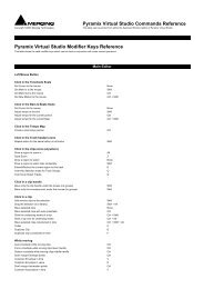
- Page 560 and 561: Appendix I - Mouse Modifier KeysMai
- Page 562 and 563: NotesLeft Mouse ButtonDrag the note
- Page 564 and 565:
ExamplesProject @ 192kHzAES II SRCS
- Page 566 and 567:
TASCAM TDIFThe TASCAM TDIF daughter
- Page 568 and 569:
PlatformThis drop-down list determi
- Page 570 and 571:
Buses Mode and DSP AllocationWhen P
- Page 572 and 573:
Bussing CapabilitiesNote 1Bussing c
- Page 574 and 575:
Settings > All Settings > Formats &
- Page 576 and 577:
Cue Sequencer ControlThe Cue Sequen
- Page 578 and 579:
Appendix VII - Mykerinos Latencies1
- Page 580 and 581:
IPCONFIG followed by Enter. The IP
- Page 582 and 583:
Appendix IX - Pyramix iXML Implemen
- Page 584 and 585:
Numerics2,3 and 4 Point Edits 1359-
- Page 586 and 587:
Composition LibraryLibrariesComposi
- Page 588 and 589:
Fixed Cursor Settings 522Fixed or M
- Page 590 and 591:
Window 216Meter Decay integration t
- Page 592 and 593:
Record ModeSafety 104Record Name 10
- Page 594 and 595:
TTab Windows 430Tail to Beginning 1