

Xilinx UG194 Virtex-5 FPGA Embedded Tri-Mode Ethernet MAC ...
Xilinx UG194 Virtex-5 FPGA Embedded Tri-Mode Ethernet MAC ...
Xilinx UG194 Virtex-5 FPGA Embedded Tri-Mode Ethernet MAC ...

Create successful ePaper yourself
Turn your PDF publications into a flip-book with our unique Google optimized e-Paper software.
Chapter 6: Physical Interface<br />
PHYE<strong>MAC</strong>#MIITXCLK and PHYE<strong>MAC</strong>#RXCLK ports of the <strong>Ethernet</strong> <strong>MAC</strong>. It is also<br />
used to clock both receiver and transmitter logic for the 16-bit <strong>Ethernet</strong> <strong>MAC</strong> client<br />
interface and the RXUSRCLK and TXUSRCLK inputs of the GTX transceiver.<br />
The global clock sourced from DCM CLKFX, running at 250 MHz, must be routed back to<br />
the <strong>Ethernet</strong> <strong>MAC</strong> through the input ports CLIENTE<strong>MAC</strong>#RXCLIENTCLKIN and<br />
CLIENTE<strong>MAC</strong>#TXCLIENTCLKIN. This clock is also connected to the<br />
PHYE<strong>MAC</strong>#GTXCLK input of the <strong>Ethernet</strong> <strong>MAC</strong> and the RXUSRCLK2 and TXUSRCLK2<br />
inputs of the transceiver.<br />
The PLLLKDET signal from the RocketIO serial transceiver (indicating that its internal<br />
PLLs have locked) is ANDed with the locked signal from the DCM and routed to the<br />
CLIENTE<strong>MAC</strong>#DCMLOCKED input port of the <strong>Ethernet</strong> <strong>MAC</strong>. This ensures that the state<br />
machines of the <strong>Ethernet</strong> <strong>MAC</strong> are held in reset until the RocketIO serial transceiver has<br />
locked and all clocks are running cleanly.<br />
As described in “<strong>Ethernet</strong> <strong>MAC</strong> Clock Generation,” page 206, the following clock signals<br />
are unused and can be left unconnected:<br />
E<strong>MAC</strong>#CLIENTRXCLIENTCLKOUT<br />
E<strong>MAC</strong>#PHYTXGMIIMIICLKOUT<br />
E<strong>MAC</strong>#CLIENTTXCLIENTCLKOUT<br />
1000BASE-X Auto-Negotiation<br />
Overview of Operation<br />
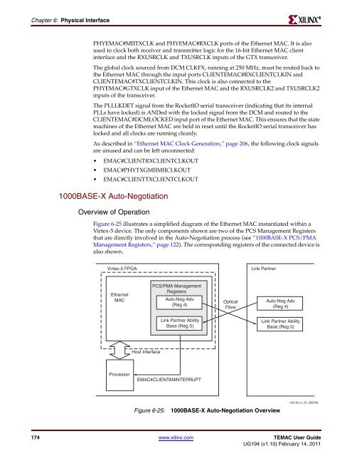
Figure 6-25 illustrates a simplified diagram of the <strong>Ethernet</strong> <strong>MAC</strong> instantiated within a<br />
<strong>Virtex</strong>-5 device. The only components shown are two of the PCS Management Registers<br />
that are directly involved in the Auto-Negotiation process (see “1000BASE-X PCS/PMA<br />
Management Registers,” page 122). The corresponding registers of the connected device is<br />
also shown.<br />
<strong>Virtex</strong>-5 <strong>FPGA</strong><br />
<strong>Ethernet</strong><br />
<strong>MAC</strong><br />
Processor<br />
Host Interface<br />
PCS/PMA Management<br />
Registers<br />
Auto-Neg Adv<br />
(Reg 4)<br />
Link Partner Ability<br />
Base (Reg 5)<br />
E<strong>MAC</strong>#CLIENTANINTERRUPT<br />
Figure 6-25: 1000BASE-X Auto-Negotiation Overview<br />
174 www.xilinx.com TE<strong>MAC</strong> User Guide<br />
<strong>UG194</strong> (v1.10) February 14, 2011<br />
Optical<br />
Fibre<br />
Link Partner<br />
Auto-Neg Adv<br />
(Reg 4)<br />
Link Partner Ability<br />
Base (Reg 5)<br />
<strong>UG194</strong>_6_25_032508<br />
R


