

Xilinx UG194 Virtex-5 FPGA Embedded Tri-Mode Ethernet MAC ...
Xilinx UG194 Virtex-5 FPGA Embedded Tri-Mode Ethernet MAC ...
Xilinx UG194 Virtex-5 FPGA Embedded Tri-Mode Ethernet MAC ...

You also want an ePaper? Increase the reach of your titles
YUMPU automatically turns print PDFs into web optimized ePapers that Google loves.
Chapter 3: Client Interface<br />
Normal Frame Reception<br />
CLIENTE<strong>MAC</strong>#RXCLIENTCLKIN<br />
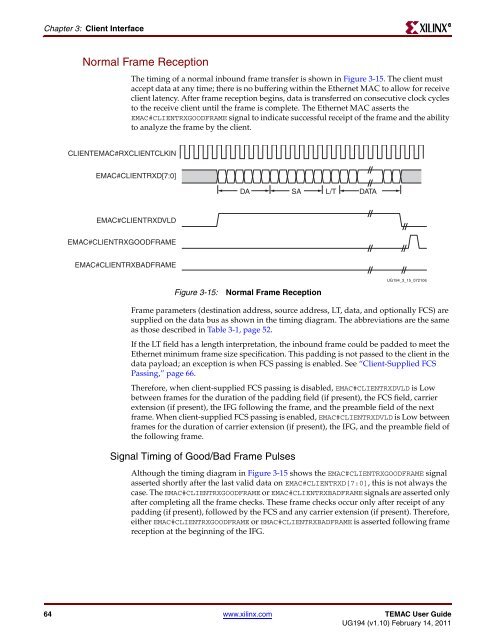
The timing of a normal inbound frame transfer is shown in Figure 3-15. The client must<br />
accept data at any time; there is no buffering within the <strong>Ethernet</strong> <strong>MAC</strong> to allow for receive<br />
client latency. After frame reception begins, data is transferred on consecutive clock cycles<br />
to the receive client until the frame is complete. The <strong>Ethernet</strong> <strong>MAC</strong> asserts the<br />
E<strong>MAC</strong>#CLIENTRXGOODFRAME signal to indicate successful receipt of the frame and the ability<br />
to analyze the frame by the client.<br />
E<strong>MAC</strong>#CLIENTRXD[7:0]<br />
E<strong>MAC</strong>#CLIENTRXDVLD<br />
E<strong>MAC</strong>#CLIENTRXGOODFRAME<br />
E<strong>MAC</strong>#CLIENTRXBADFRAME<br />
Figure 3-15: Normal Frame Reception<br />
Frame parameters (destination address, source address, LT, data, and optionally FCS) are<br />
supplied on the data bus as shown in the timing diagram. The abbreviations are the same<br />
as those described in Table 3-1, page 52.<br />
If the LT field has a length interpretation, the inbound frame could be padded to meet the<br />
<strong>Ethernet</strong> minimum frame size specification. This padding is not passed to the client in the<br />
data payload; an exception is when FCS passing is enabled. See “Client-Supplied FCS<br />
Passing,” page 66.<br />
Therefore, when client-supplied FCS passing is disabled, E<strong>MAC</strong>#CLIENTRXDVLD is Low<br />
between frames for the duration of the padding field (if present), the FCS field, carrier<br />
extension (if present), the IFG following the frame, and the preamble field of the next<br />
frame. When client-supplied FCS passing is enabled, E<strong>MAC</strong>#CLIENTRXDVLD is Low between<br />
frames for the duration of carrier extension (if present), the IFG, and the preamble field of<br />
the following frame.<br />
Signal Timing of Good/Bad Frame Pulses<br />
DA SA L/T DATA<br />
<strong>UG194</strong>_3_15_072106<br />
Although the timing diagram in Figure 3-15 shows the E<strong>MAC</strong>#CLIENTRXGOODFRAME signal<br />
asserted shortly after the last valid data on E<strong>MAC</strong>#CLIENTRXD[7:0], this is not always the<br />
case. The E<strong>MAC</strong>#CLIENTRXGOODFRAME or E<strong>MAC</strong>#CLIENTRXBADFRAME signals are asserted only<br />
after completing all the frame checks. These frame checks occur only after receipt of any<br />
padding (if present), followed by the FCS and any carrier extension (if present). Therefore,<br />
either E<strong>MAC</strong>#CLIENTRXGOODFRAME or E<strong>MAC</strong>#CLIENTRXBADFRAME is asserted following frame<br />
reception at the beginning of the IFG.<br />
64 www.xilinx.com TE<strong>MAC</strong> User Guide<br />
<strong>UG194</strong> (v1.10) February 14, 2011<br />
R


