Xilinx UG194 Virtex-5 FPGA Embedded Tri-Mode Ethernet MAC ...
Xilinx UG194 Virtex-5 FPGA Embedded Tri-Mode Ethernet MAC ...
Xilinx UG194 Virtex-5 FPGA Embedded Tri-Mode Ethernet MAC ...
You also want an ePaper? Increase the reach of your titles
YUMPU automatically turns print PDFs into web optimized ePapers that Google loves.
R<br />
GMII (Byte PHY) <strong>Mode</strong><br />
Clock Definitions and Frequencies<br />
The clock signal input into PHYE<strong>MAC</strong>#RXCLK is sourced by the external PHY device at<br />
1 Gb/s. At 10/100 Mb/s speeds, this clock should also originate from the external PHY<br />
device but its frequency is divided by two in the <strong>FPGA</strong> logic (see “GMII Clock<br />
Management for <strong>Tri</strong>-Speed Operation Using Byte PHY”). The resultant clock should be<br />
used by the <strong>FPGA</strong> logic to clock the receiver client and physical interface logic. Internally<br />
in the <strong>Ethernet</strong> <strong>MAC</strong>, this clock is used to derive all physical and client receiver clocks.<br />
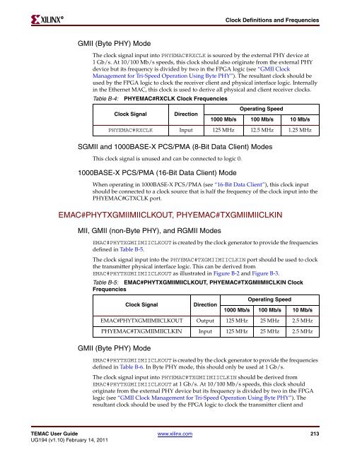
Table B-4: PHYE<strong>MAC</strong>#RXCLK Clock Frequencies<br />
Clock Signal Direction<br />
SGMII and 1000BASE-X PCS/PMA (8-Bit Data Client) <strong>Mode</strong>s<br />
This clock signal is unused and can be connected to logic 0.<br />
1000BASE-X PCS/PMA (16-Bit Data Client) <strong>Mode</strong><br />
When operating in 1000BASE-X PCS/PMA (see “16-Bit Data Client”), this clock input<br />
should be connected to a clock source that is half the frequency of the clock input into the<br />
PHYE<strong>MAC</strong>#GTXCLK port.<br />
E<strong>MAC</strong>#PHYTXGMIIMIICLKOUT, PHYE<strong>MAC</strong>#TXGMIIMIICLKIN<br />
MII, GMII (non-Byte PHY), and RGMII <strong>Mode</strong>s<br />
E<strong>MAC</strong>#PHYTXGMIIMIICLKOUT is created by the clock generator to provide the frequencies<br />
defined in Table B-5.<br />
The clock signal input into the PHYE<strong>MAC</strong>#TXGMIIMIICLKIN port should be used to clock<br />
the transmitter physical interface logic. This can be derived from<br />
E<strong>MAC</strong>#PHYTXGMIIMIICLKOUT as illustrated in Figure B-2 and Figure B-3.<br />
GMII (Byte PHY) <strong>Mode</strong><br />
Operating Speed<br />
1000 Mb/s 100 Mb/s 10 Mb/s<br />
PHYE<strong>MAC</strong>#RXCLK Input 125 MHz 12.5 MHz 1.25 MHz<br />
Table B-5: E<strong>MAC</strong>#PHYTXGMIIMIICLKOUT, PHYE<strong>MAC</strong>#TXGMIIMIICLKIN Clock<br />
Frequencies<br />
Clock Signal Direction<br />
Operating Speed<br />
1000 Mb/s 100 Mb/s 10 Mb/s<br />
E<strong>MAC</strong>#PHYTXGMIIMIICLKOUT Output 125 MHz 25 MHz 2.5 MHz<br />
PHYE<strong>MAC</strong>#TXGMIIMIICLKIN Input 125 MHz 25 MHz 2.5 MHz<br />
E<strong>MAC</strong>#PHYTXGMIIMIICLKOUT is created by the clock generator to provide the frequencies<br />
defined in Table B-6. In Byte PHY mode, this should only be used at 1 Gb/s.<br />
The clock signal input into PHYE<strong>MAC</strong>#TXGMIIMIICLKIN should be derived from<br />
E<strong>MAC</strong>#PHYTXGMIIMIICLKOUT at 1 Gb/s. At 10/100 Mb/s speeds, this clock should<br />
originate from the external PHY device but its frequency is divided by two in the <strong>FPGA</strong><br />
logic (see “GMII Clock Management for <strong>Tri</strong>-Speed Operation Using Byte PHY”). The<br />
resultant clock should be used by the <strong>FPGA</strong> logic to clock the transmitter client and<br />
TE<strong>MAC</strong> User Guide www.xilinx.com 213<br />
<strong>UG194</strong> (v1.10) February 14, 2011


