

Xilinx UG194 Virtex-5 FPGA Embedded Tri-Mode Ethernet MAC ...
Xilinx UG194 Virtex-5 FPGA Embedded Tri-Mode Ethernet MAC ...
Xilinx UG194 Virtex-5 FPGA Embedded Tri-Mode Ethernet MAC ...

You also want an ePaper? Increase the reach of your titles
YUMPU automatically turns print PDFs into web optimized ePapers that Google loves.
R<br />
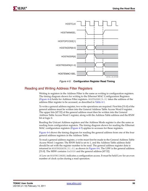
HOSTCLK<br />
HOSTMIIMSEL<br />
HOSTOPCODE[1]<br />
HOSTADDR[8:0]<br />
HOSTADDR[9]<br />
HOSTRDDATA[31:0]<br />
HOSTE<strong>MAC</strong>1SEL<br />
Figure 4-5: Configuration Register Read Timing<br />
Reading and Writing Address Filter Registers<br />
<strong>UG194</strong>_4_05_051308<br />
Using the Host Bus<br />
Writing to registers in the Address Filter is the same as writing to configuration registers.<br />
The timing diagram shown for writing to the <strong>Ethernet</strong> <strong>MAC</strong> Configuration Registers<br />
(Figure 4-4) holds for Address Filter registers. HOSTADDR[9:0] takes the address of the<br />
address filter register to be accessed, as described in Table 4-1.<br />
To write a general address register, two write operations are required. First bits [31:0] of the<br />
general address must be written into the General Address Table Access Word 0 register.<br />
The upper bits [47:32] of the general address must then be written into the General<br />
Address Table Access Word 1 register, along with the Address Table address and the RNW<br />
bit at logic 0.<br />
Reading the Unicast Address registers and the Address <strong>Mode</strong> register is also the same as<br />
reading from configuration registers. The timing diagram shown for reading the <strong>Ethernet</strong><br />
<strong>MAC</strong> configuration registers (Figure 4-5) applies to accesses for these registers.<br />
Figure 4-6 shows the timing diagram for reading the general address from one of the four<br />
general address registers in the Address Table.<br />
To read a general address register, a write must first be made to the General Address Table<br />
Access Word 1 register. The RNW field is set to 1, and the Address Table address field<br />
should be set with the register number to be read. The general address register data is<br />
returned in HOSTRDDATA[31:0] as shown in Figure 4-6. The LSW is the general address<br />
[31:0]. The MSW contains 0x0000 and the general address [47:32].<br />
A Low on HOSTMIIMSEL indicates a configuration access. It must be held Low for an even<br />
number of clock cycles during a read operation.<br />
TE<strong>MAC</strong> User Guide www.xilinx.com 99<br />
<strong>UG194</strong> (v1.10) February 14, 2011


