AT Command Reference Guide for EDGE Wireless ... - wless.ru
AT Command Reference Guide for EDGE Wireless ... - wless.ru
AT Command Reference Guide for EDGE Wireless ... - wless.ru
You also want an ePaper? Increase the reach of your titles
YUMPU automatically turns print PDFs into web optimized ePapers that Google loves.
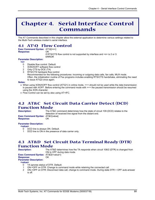
Chapter 4 – Serial Interface Control <strong>Command</strong>s<br />
Chapter 4. Serial Interface Control<br />
<strong>Command</strong>s<br />
The <strong>AT</strong> <strong>Command</strong>s described in this chapter allow the external application to determine various settings related to<br />
the Multi-Tech wireless modem’s serial interface.<br />
4.1 <strong>AT</strong>\Q Flow Control<br />
Exec <strong>Command</strong> Syntax: <strong>AT</strong>\Q[]<br />
Response:<br />
OK<br />
If RTS/CTS flow control is not supported by interface and is 2 or 3:<br />
ERROR<br />
Parameter Description:<br />
<br />
0 Disable flow control. Default.<br />
1 XON/XOFF software flow control<br />
2 Only CTS by DCE (TA)<br />
3 RTS/CTS hardware flow control<br />
Recommended <strong>for</strong> the following procedures: incoming or outgoing data calls, fax calls, MUX mode.<br />
Often, the initialization routine of Fax programs includes enabling RTS/CTS handshake, eliminating the need<br />
to issue <strong>AT</strong>\Q3 once again.<br />
Notes:<br />
• When using XON/XOFF flow control (<strong>AT</strong>\Q1) in online mode, +++ should not be used while the data transmission<br />
is paused with XOFF. Be<strong>for</strong>e entering the command mode with +++ the paused transmission should be resumed<br />
using the XON character.<br />
• Flow Control can be set by also using <strong>AT</strong>+IFC.<br />
4.2 <strong>AT</strong>&C Set Circuit Data Carrier Detect (DCD)<br />
Function Mode<br />
Description:<br />
Exec <strong>Command</strong> Syntax: <strong>AT</strong>&C[value]<br />
Response:<br />
OK<br />
The <strong>AT</strong>&C command determines how the state of circuit 109 (DCD) relates to the<br />
detection of received line signal from the distant end.<br />
Parameter Description:<br />
<br />
0 DCD line is always ON. Default.<br />
1 DCD line is ON in the presence of data carrier only.<br />
4.3 <strong>AT</strong>&D Set Circuit Data Terminal Ready (DTR)<br />
Function Mode<br />
Description:<br />
The <strong>AT</strong>&D determines how the TA responds when circuit 108/2 (DTR) is changed from<br />
ON to OFF during data mode.<br />
Exec <strong>Command</strong> Syntax: <strong>AT</strong>&D[]<br />
Response:<br />
OK<br />
Parameter Description:<br />
<br />
0 TA ignores status of DTR. Default.<br />
1 ON->OFF on DTR: Change to command mode while retaining the connected call.<br />
2 ON->OFF on DTR: Disconnect data call, change to command mode. During state DTR = OFF auto-answer<br />
is off.<br />
Multi-Tech Systems, Inc. <strong>AT</strong> <strong>Command</strong>s <strong>for</strong> <strong>EDGE</strong> Modems (S000371B) 51


