AT Command Reference Guide for EDGE Wireless ... - wless.ru
AT Command Reference Guide for EDGE Wireless ... - wless.ru
AT Command Reference Guide for EDGE Wireless ... - wless.ru

Create successful ePaper yourself
Turn your PDF publications into a flip-book with our unique Google optimized e-Paper software.
Chapter 4 – Serial Interface Control <strong>Command</strong>s<br />
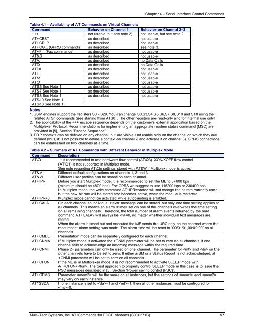
Table 4.1 – Availability of <strong>AT</strong> <strong>Command</strong>s on Virtual Channels<br />
<strong>Command</strong> Behavior on Channel 1 Behavior on Channel 2=3<br />
+++ not usable, but see note 2) not usable, but see note 2<br />
<strong>AT</strong>+CBST as described not usable<br />
<strong>AT</strong>+CRLP as described not usable<br />
<strong>AT</strong>+CG... (GPRS commands) as described see note 3.<br />
<strong>AT</strong>+F... (Fax commands) as described not usable<br />
<strong>AT</strong>&S as described not usable<br />
<strong>AT</strong>A as described no Data Calls<br />
<strong>AT</strong>D as described no Data Calls<br />
<strong>AT</strong>DI as described not usable<br />
<strong>AT</strong>L as described not usable<br />
<strong>AT</strong>M as described not usable<br />
<strong>AT</strong>O as described not usable<br />
<strong>AT</strong>S6 See Note 1 as described not usable<br />
<strong>AT</strong>S7 See Note 1 as described not usable<br />
<strong>AT</strong>S8 See Note 1 as described not usable<br />
<strong>AT</strong>S10 See Note 1<br />
<strong>AT</strong>S18 See Note 1<br />
Notes:<br />
1. GSM engines support the registers S0 - S29. You can change S0,S3,S4,S5,S6,S7,S8,S10 and S18 using the<br />
related <strong>AT</strong>Sn commands (see starting from <strong>AT</strong>S0). The other registers are read-only and <strong>for</strong> internal use only!<br />
2. The applicability of the +++ escape sequence depends on the customer’s external application based on the<br />
Mulitplexer Protocol. Recommendations <strong>for</strong> implementing an appropriate modem status command (MSC) are<br />
provided in [5], Section “Escape Sequence”.<br />
3. PDP contexts can be defined on any channel, but are visible and usable only on the channel on which they are<br />
defined (thus, it is not possible to define a context on channel 2 and activate it on channel 3). GPRS connections<br />
can be established on two channels at a time.<br />
Table 4.2 – Summary of <strong>AT</strong> <strong>Command</strong>s with Different Behavior in Multiplex Mode<br />
<strong>Command</strong> Description<br />
<strong>AT</strong>\Q It is recommended to use hardware flow control (<strong>AT</strong>\Q3). XON/XOFF flow control<br />
(<strong>AT</strong>\Q1) is not supported in Multiplex mode.<br />
See note regarding <strong>AT</strong>\Qn settings stored with <strong>AT</strong>&W if Multiplex mode is active.<br />
<strong>AT</strong>&V Different default configurations on channels 1, 2 and 3.<br />
<strong>AT</strong>&W Different user profiles can be stored on each channel.<br />
<strong>AT</strong>+IPR Be<strong>for</strong>e you start Multiplex mode, it is recommended to set the ME to 57600 bps<br />
(minimum should be 4800 bps). For GPRS we suggest to use 115200 bps or 230400 bps.<br />
In Multiplex mode, the write command <strong>AT</strong>+IPR= will not change the bit rate currently used,<br />
but the new bit rate will be stored and becomes active, when the module is restarted.<br />
<strong>AT</strong>+IPR=0 Multiplex mode cannot be activated while autobauding is enabled.<br />
<strong>AT</strong>+CALA On each channel an individual message can be stored. but only one time setting applies to<br />
all channels. This means an alarm set on one of the channels overwrites the time setting<br />
on all remaining channels. There<strong>for</strong>e, the total number of alarm events returned by the read<br />
command <strong>AT</strong>+CALA will always be =0, no matter whether individual text messages are<br />
stored.<br />
When the alarm is timed out and executed the ME sends the URC only on the channel where the<br />
most recent alarm setting was made. The alarm time will be reset to “00/01/01,00:00:00” on all<br />
channels.<br />
<strong>AT</strong>+CMEE Presentation mode can be separately configured <strong>for</strong> each channel.<br />
<strong>AT</strong>+CNMA If Multiplex mode is activated the +CNMI parameter will be set to zero on all channels, if one<br />
channel fails to acknowledge an incoming message within the required time.<br />
<strong>AT</strong>+CNMI Phase 2+ parameters can only be used on one channel. The parameter <strong>for</strong> and on the<br />
other channels have to be set to zero. If either a SM or a Status Report is not acknowledged, all<br />
+CNMI parameter will be set to zero on all channels.<br />
<strong>AT</strong>+CFUN If the ME is in Multiplexer mode, it is not recommended to activate SLEEP mode with<br />
<strong>AT</strong>+CFUN=. The best approach to properly control SLEEP mode in this case is to issue the<br />
PSC messages described in [5], Section “Power saving control (PSC)”.<br />
<strong>AT</strong>+CPMS Parameter will be the same on all instances, but the settings of and <br />
may vary on each instance.<br />
<strong>AT</strong>^SSDA If one instance is set to =1 and =1, then all other instances must be configured <strong>for</strong><br />
=0.<br />
Multi-Tech Systems, Inc. <strong>AT</strong> <strong>Command</strong>s <strong>for</strong> <strong>EDGE</strong> Modems (S000371B) 57