- Page 1 and 2:
AIR CONDITIONER (MULTI TYPE) SERVIC
- Page 3 and 4:
4-1. Normal Operation (COOL Mode /
- Page 5 and 6:
9-4. Cooling-Season Outdoor Unit Ba
- Page 7 and 8:
Definition of Protective Gear When
- Page 9 and 10:
Precautions for Safety The manufact
- Page 11 and 12:
Use specified parts. When any of th
- Page 13 and 14:
Only a qualified installer (*1) or
- Page 15 and 16:
Specifications Model MMY-MAP0804HT8
- Page 17 and 18:
Carrying in the Outdoor Unit CAUTIO
- Page 19 and 20:
Selection of Pipe Size Coupling siz
- Page 21 and 22:
Table 2 Standard type High Efficien
- Page 23 and 24:
4. Tools (1) Required Tools for R41
- Page 25 and 26:
Models: MMY-MAP1404* and MAP1604 *
- Page 27 and 28:
1-2-2. Compact 4-way Cassette Type
- Page 29 and 30:
1-2-4. 1-way Air Discharge Cassette
- Page 31 and 32:
1-2-6. 2-way Air Discharge Cassette
- Page 33 and 34:
1-2-8. Concealed Duct High Static P
- Page 35 and 36:
1-2-9. Slim Duct Type Models: MMD-A
- Page 37 and 38:
1-2-11.High Wall Type 2 series Mode
- Page 39 and 40:
1-2-13.Floor Standing Cabinet Type
- Page 41 and 42:
1-2-15.Floor Standing Type Models:
- Page 43 and 44:
Models: MMD-AP0721HFE and MMD-AP096
- Page 45 and 46:
2-2. Outdoor Unit (60Hz model: MMY-
- Page 47 and 48:
2-4. Outdoor Inverter (60Hz model:
- Page 49 and 50:
2-way Air Discharge Cassette Type M
- Page 51 and 52:
Concealed Duct High Static Pressure
- Page 53 and 54:
Floor Standing Type Model MMF-AP 01
- Page 55 and 56:
14, 16HP Model: MMY-MAP1404* , MAP1
- Page 57 and 58:
Outdoor Unit (14, 16HP) Model: MMY-
- Page 59 and 60:
2-8-2. Inverter P.C. board for comp
- Page 61 and 62:
3 Refrigerant Piping Systematic Dra
- Page 63 and 64: Explanation of Functional Parts Fun
- Page 65 and 66: 4 Combined Refrigerant Piping Syste
- Page 67 and 68: 4-3. Normal Operation (HEAT Mode) H
- Page 69 and 70: 4-5. Emergency Operation (Heating O
- Page 71 and 72: 5 Control Outline Indoor Unit Cont
- Page 73 and 74: NO. Item Specification outline Rema
- Page 75 and 76: NO. Item Specification outline Rema
- Page 77 and 78: Outdoor Unit Item Description of op
- Page 79 and 80: Item Description of operation, nume
- Page 81 and 82: Item Description of operation, nume
- Page 83 and 84: Item Description of operation, nume
- Page 85 and 86: 1 Cooling operation under low outsi
- Page 87 and 88: Central control remote controller (
- Page 89 and 90: 6-1-2. When Wireless Remote Control
- Page 91 and 92: Central control remote controller (
- Page 93 and 94: X Y DC5V Power supply circuit Main
- Page 95 and 96: 6-2. Indoor Printed Circuit Board M
- Page 97 and 98: MCC-1403 Power supply Power supply
- Page 99 and 100: 6-4. Test Operation of Indoor Unit
- Page 101 and 102: Function CODE No. (DN Code) Table (
- Page 103 and 104: Type DN code “10” Value Type Mo
- Page 105 and 106: ▼ Ventilating fan control from re
- Page 107 and 108: 6-7. Applied control for Outdoor Un
- Page 109 and 110: (2) Indoor unit setup method for pr
- Page 111 and 112: 6-8-1. Power peak-cut Control (Stan
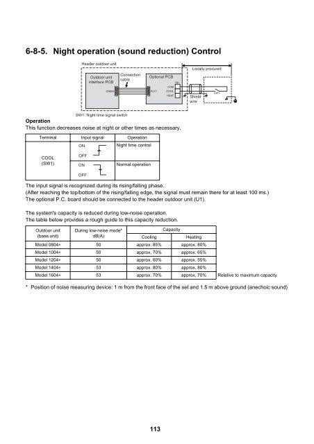
- Page 113: 6-8-3. Snowfall Fan Control Header
- Page 117 and 118: 6-8-8. Compressor Operation Output
- Page 119 and 120: 7 TEST OPERATION 7-1. Procedure and
- Page 121 and 122: (2) In the case that a central cont
- Page 123 and 124: • Check the additional amount of
- Page 125 and 126: 7-4. Address Setup This product req
- Page 127 and 128: (Example) Controlling 2 or more ref
- Page 129 and 130: 10 Set the central control address.
- Page 131 and 132: Manual address setup from the remot
- Page 133 and 134: To find an indoor unit’s position
- Page 135 and 136: 4 Push the TIME / buttons repeatedl
- Page 137 and 138: 2) Turn on dip switch 2 of SW30 on
- Page 139 and 140: 7-4-4. Check after Address Setup wh
- Page 141 and 142: 7-5-2. Operation from the indoor re
- Page 143 and 144: Miswiring example Figure Remote con
- Page 145 and 146: 7-6-2. Cooling/Heating Test Operati
- Page 147 and 148: (2) Test operation START Test opera
- Page 149 and 150: 7-7. Service Support Function 7-7-1
- Page 151 and 152: 7-7-2. Function to Start/Stop (ON/O
- Page 153 and 154: (2) Heating test operation function
- Page 155 and 156: (4) Individual start/stop (ON/OFF)
- Page 157 and 158: (2)Clearing error by using switches
- Page 159 and 160: 7-7-5. Pulse Motor Valve (PMV) Forc
- Page 161 and 162: 7-7-8. Fan Operation Check in Outdo
- Page 163 and 164: 7-7-10.Manual Adjustment Function o
- Page 165 and 166:
7-7-11.Monitor Function of Remote C
- Page 167 and 168:
8 TROUBLESHOOTING 8-1. Overview (1)
- Page 169 and 170:
(Error detected by main remote cont
- Page 171 and 172:
F12 - F12 ALT F15 - F15 ALT F16 - F
- Page 173 and 174:
(Errors detected by IPDU featuring
- Page 175 and 176:
Using TCC-LINK central control remo
- Page 177 and 178:
Light block Check code Cause of fau
- Page 179 and 180:
8-4. Check Codes Displayed on Remot
- Page 181 and 182:
Main remote controller Check code O
- Page 183 and 184:
Main remote controller Check code O
- Page 185 and 186:
Main remote controller Check code O
- Page 187 and 188:
Main remote controller Check code O
- Page 189 and 190:
Main remote controller P04 P05 P07
- Page 191 and 192:
Main remote controller Check code O
- Page 193 and 194:
Errors Detected by TCC-LINK Central
- Page 195 and 196:
8-5. Diagnosis procedure for each c
- Page 197 and 198:
Check code Check code name Cause Ch
- Page 199 and 200:
Check code Check code name Cause [E
- Page 201 and 202:
Check code Check code name Cause [E
- Page 203 and 204:
Check code Check code name Cause [F
- Page 205 and 206:
Check code Check code name Cause [H
- Page 207 and 208:
Check code Check code name Cause [H
- Page 209 and 210:
(*3) Check for solenoid valve of al
- Page 211 and 212:
Check code Check code name Cause [H
- Page 213 and 214:
Check code Check code name Cause [H
- Page 215 and 216:
Check code Check code name Cause [L
- Page 217 and 218:
Check code Check code name Cause [P
- Page 219 and 220:
Check code Check code name Cause [P
- Page 221 and 222:
Check code Check code name Cause [P
- Page 223 and 224:
(C) Heating operation Does heating
- Page 225 and 226:
Check code Check code name Cause [P
- Page 227 and 228:
(1)Display of System Information (D
- Page 229 and 230:
(3)Display of Outdoor Cycle Data (D
- Page 231 and 232:
(5)Display of Indoor Unit Informati
- Page 233 and 234:
8-8. Leakage/Clogging of Refrigerat
- Page 235 and 236:
List of Check Codes Generated upon
- Page 237 and 238:
8-9. Sensor Characteristics Outdoor
- Page 239 and 240:
Indoor TC1 sensor 200 150 Resistanc
- Page 241 and 242:
240 Outdoor Unit ▼ Ps sensor char
- Page 243 and 244:
9-2. Compressor Backup Operation Se
- Page 245 and 246:
(6) Turn on the power supply to all
- Page 247 and 248:
(8) Set Bits 1 and 2 of SW30 on the
- Page 249 and 250:
10OUTDOOR UNIT REFRIGERANT RECOVERY
- Page 251 and 252:
[Setup of failed outdoor unit] (13)
- Page 253 and 254:
[Setup of outdoor units other than
- Page 255 and 256:
10-3.Work procedure after Repair Wh
- Page 257 and 258:
11-2.Replacement of Compressors
- Page 259 and 260:
[When replacing normal as well as f
- Page 261 and 262:
11-3.Check Procedure to Search Caus
- Page 263 and 264:
Check items and procedures to follo
- Page 265 and 266:
No. Part to be replaced Work proced
- Page 267 and 268:
No. Part to be replaced Work proced
- Page 269 and 270:
No. Part to be replaced Work proced
- Page 271 and 272:
No. Part to be replaced Work proced
- Page 273 and 274:
No. Part to be replaced Work proced
- Page 275 and 276:
No. Part to be replaced Work proced
- Page 277 and 278:
13P.C. BOARD EXCHANGE PROCEDURES I
- Page 279 and 280:
Procedure 1: Reading Setting Data f
- Page 281 and 282:
Procedure 3: Writing Setting Data i
- Page 283 and 284:
CODE No. list (Example) CODE No. (D
- Page 285 and 286:
13-2-3.Interface board (MCC-1606) r
- Page 287 and 288:
(6) Set the dip switch (SW800) sett
- Page 289 and 290:
13-2-6.Noise Filter P.C. Board (MCC
- Page 291 and 292:
(7) Install the service P.C. boards
- Page 293 and 294:
292
- Page 295 and 296:
SMMS-i OUTDOOR UNIT MMY-MAP1404HT8(
- Page 297 and 298:
REFRIGERATION CIRCUIT DIAGRAM M MOT
- Page 299 and 300:
Ref. No. Part No. Description MAP08
- Page 301 and 302:
SMMS-i INV SERVICE PARTS LIST MMY-M
- Page 303 and 304:
SMMS-i OUTDOOR UNIT MMY-MAP0804T8(Z
- Page 305 and 306:
REFRIGERATION CIRCUIT DIAGRAM M MOT
- Page 307 and 308:
306
- Page 309 and 310:
Ref. No. Part No. Description MAP08
- Page 311 and 312:
SMMS-i INV SERVICE PARTS LIST MMY-M
- Page 313 and 314:
Ref. No. Part No. Description MAP08
- Page 315 and 316:
314
- Page 317 and 318:
SMMS-i OUTDOOR UNIT MMY-MAP1404HT8(
- Page 319 and 320:
REFRIGERATION CIRCUIT DIAGRAM M MOT
- Page 321 and 322:
Ref. No. Part No. Description MAP08
- Page 323 and 324:
SMMS-i INV SERVICE PARTS LIST MMY-M
- Page 325 and 326:
SMMS-i OUTDOOR UNIT MMY-MAP0804T8(Z
- Page 327 and 328:
REFRIGERATION CIRCUIT DIAGRAM M MOT
- Page 329 and 330:
328
- Page 331 and 332:
Ref. No. Part No. Description MAP08
- Page 333 and 334:
SMMS-i INV SERVICE PARTS LIST MMY-M
- Page 335 and 336:
Ref. No. Part No. Description MAP08
- Page 337 and 338:
336
- Page 339 and 340:
SMMS-i OUTDOOR UNIT MMY-MAP1404HT8(
- Page 341 and 342:
REFRIGERATION CIRCUIT DIAGRAM M MOT
- Page 343 and 344:
Ref. No. Part No. Description MAP08
- Page 345 and 346:
SMMS-i INV SERVICE PARTS LIST MMY-M
- Page 347 and 348:
SMMS-i OUTDOOR UNIT MMY-MAP0804HT7(
- Page 349 and 350:
REFRIGERATION CIRCUIT DIAGRAM M MOT
- Page 351 and 352:
350
- Page 353 and 354:
Ref. No. Part No. Description MAP08
- Page 355 and 356:
SMMS-i INV SERVICE PARTS LIST MMY-M
- Page 357 and 358:
Ref. No. Part No. Description MAP08
- Page 359 and 360:
358
- Page 361 and 362:
SMMS-i OUTDOOR UNIT MMY-MAP1404T8-S
- Page 363 and 364:
REFRIGERATION CIRCUIT DIAGRAM M MOT
- Page 365 and 366:
Ref. No. Part No. Description MAP08
- Page 367 and 368:
SMMS-i INV SERVICE PARTS LIST MMY-M
- Page 369 and 370:
WARNINGS ON REFRIGERANT LEAKAGE Che