MULTI TYPE
MULTI TYPE
MULTI TYPE

Create successful ePaper yourself
Turn your PDF publications into a flip-book with our unique Google optimized e-Paper software.
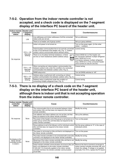
7-5-2. Operation from the indoor remote controller is not<br />
accepted, and a check code is displayed on the 7-segment<br />
display of the interface PC board of the header unit.<br />
Indoor remote<br />
controller<br />
status<br />
No response<br />
Header unit<br />
7-segment<br />
display<br />
L08<br />
E19 -00<br />
Alternate<br />
blinking<br />
E19 -02<br />
Alternate<br />
blinking<br />
E20 -01<br />
Alternate<br />
blinking<br />
Cause<br />
Line addresses and indoor addresses of all the connected<br />
indoor units are not set.<br />
There is no header unit of group control.<br />
Indoor unit power is not turned on.<br />
Indoor/outdoor communication line is not correctly connected<br />
to the U1/U2 terminal of the header unit ( Fig. 1). (Indoor/<br />
outdoor cannot communicate before address setup.)<br />
There is no of outdoor terminal resistance, or there<br />
are two or more resistances (before address setup).<br />
When connecting an indoor/outdoor communication line<br />
between outdoor units under the condition of a connected<br />
communication line between outdoor units ( Fig. 2).<br />
SW08 setup error<br />
ON<br />
1 2<br />
SW30<br />
Address setup is performed with connecting an indoor/<br />
outdoor communication line between outdoor units ( Fig. 3).<br />
Address setup is performed under the condition of<br />
connecting multiple refrigerant lines ( Fig. 3).<br />
Set up addresses.<br />
Countermeasures<br />
Set up a group address.<br />
Turn on the power again. (In the order:<br />
indoor ➝ outdoor)<br />
Correct wiring<br />
Check SW30 bit 2 of the header unit.<br />
No connection between multiple refrigerant<br />
lines: SW30 bit 2 is on.<br />
Connection between multiple refrigerant<br />
lines: SW30 bit 2 of the connected header<br />
unit is turned on only for one line.<br />
Correct wiring<br />
Turn all SW08 switches to “off.”<br />
Correct wiring<br />
Correct wiring<br />
7-5-3. There is no display of a check code on the 7-segment<br />
display on the interface PC board of the header unit,<br />
although there is indoor unit that is not accepting operation<br />
from the indoor remote controller.<br />
Indoor remote<br />
controller<br />
status<br />
Header unit<br />
7-segment<br />
display<br />
Cause<br />
Countermeasures<br />
The communication line is not connected between indoor<br />
and outdoor (the unit that does not respond to the indoor<br />
remote controller).<br />
Modify the wiring.<br />
No response<br />
None<br />
Line address and indoor address are not set (the unit that<br />
does not respond to the indoor remote controller).<br />
The power of the header unit of the group is not turned on in<br />
indoor group control (the unit that does not respond to the<br />
indoor remote controller).<br />
Set up the address.<br />
Turn on the power.<br />
Group address is set to the follower unit for individual control<br />
(the unit that does not respond to the indoor remote<br />
controller).<br />
Set the group address to “0” in the case of<br />
individual control.<br />
The power is not turned on (the unit that is not displayed on<br />
the indoor remote controller).<br />
The indoor remote controller is not connected with a wire (the<br />
unit that is not displayed on the indoor remote controller).<br />
Miswiring of the indoor remote controller (the unit that is not<br />
displayed on the indoor remote controller)<br />
Indoor remote controller communication circuit error (the unit<br />
that is not displayed on the indoor remote controller)<br />
If 220-240 V is incorrectly applied to the indoor remote<br />
controller terminal, the remote controller communication<br />
circuit fails.<br />
Turn on the power.<br />
No display on the<br />
indoor remote<br />
controller (no line<br />
is output.)<br />
None<br />
Modify the wiring.<br />
Modify the wiring.<br />
Remove the fast-on terminal connected to<br />
indoor remote controller terminals A/B, and<br />
check the voltage. If voltage is not applied<br />
(normally 15 to 18 V), replace the PC board.<br />
140