- Page 1 and 2:
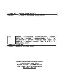
TENDER NO VOLUME PSER:SCT:DPL-C1154
- Page 3 and 4:
VOLUME-IF (SUP) TENDER NO - PSER:SC
- Page 5 and 6:
VOLUME-IF (SUP) TENDER NO - PSER:SC
- Page 7 and 8:
VOLUME-IF (SUP) TENDER NO - PSER:SC
- Page 9 and 10:
TENDER NO VOLUME PSER:SCT:DPL-C1154
- Page 11 and 12:
VOLUME-IF (SER) TENDER NO - PSER:SC
- Page 13 and 14:
VOLUME-IF (SER) TENDER NO - PSER:SC
- Page 15 and 16:
VOLUME-IF (SER) TENDER NO - PSER:SC
- Page 17 and 18:
VOLUME-IF (SER) TENDER NO - PSER:SC
- Page 19 and 20:
VOLUME-IF (SER) TENDER NO - PSER:SC
- Page 21 and 22:
VOLUME-IF (SER) TENDER NO - PSER:SC
- Page 23 and 24:
VOLUME-IF (SER) TENDER NO - PSER:SC
- Page 25 and 26:
VOLUME-IF (SER) TENDER NO - PSER:SC
- Page 27 and 28:
VOLUME-IF (SER) TENDER NO - PSER:SC
- Page 29 and 30:
VOLUME-IF (SER) TENDER NO - PSER:SC
- Page 31 and 32:
VOLUME-IF (SER) TENDER NO - PSER:SC
- Page 33 and 34:
VOLUME-IF (SER) TENDER NO - PSER:SC
- Page 35 and 36:
VOLUME-IF (SER) TENDER NO - PSER:SC
- Page 37 and 38:
VOLUME-IF (SER) TENDER NO - PSER:SC
- Page 39 and 40:
VOLUME-IF (SER) TENDER NO - PSER:SC
- Page 41 and 42:
VOLUME-IF (SER) TENDER NO - PSER:SC
- Page 43 and 44:
VOLUME-IF (SER) TENDER NO - PSER:SC
- Page 45 and 46:
THE DURGAPUR PROJECTS LIMITED DURGA
- Page 47 and 48:
SPECIFICATION NO. PE-TS-360-620-C00
- Page 49 and 50:
TITLE: SCOPE OF WORK SPECIFICATION
- Page 51 and 52:
TITLE: SCOPE OF WORK SPECIFICATION
- Page 53 and 54:
TITLE: PROJECT INFORMATION SPECIFIC
- Page 55:
TITLE: PROJECT INFORMATION SPECIFIC
- Page 60 and 61:
TITLE: TECHNICAL SPECIFICATION FOR
- Page 62 and 63:
TITLE: TECHNICAL SPECIFICATION FOR
- Page 64 and 65:
iv) TITLE: TECHNICAL SPECIFICATION
- Page 66 and 67:
TITLE: SPECIFIC TECHNICAL REQUIREME
- Page 68 and 69:
TITLE: SPECIFICATION NO. PE-TS-360-
- Page 70 and 71:
TITLE: SPECIFICATION NO. PE-TS-360-
- Page 72 and 73:
SPECIFIC TECHNICAL REQUIREMENT SPEC
- Page 74 and 75:
PEM-6666-0 TITLE SPECIFICATION NO.
- Page 76 and 77:
PEM-6666-0 TITLE SPECIFICATION NO.
- Page 78 and 79:
PEM-6666-0 TITLE SPECIFICATION NO.
- Page 80 and 81:
PEM-6666-0 TITLE SPECIFICATION NO.
- Page 82 and 83:
PEM-6666-0 TITLE SPECIFICATION NO.
- Page 84 and 85:
PEM-6666-0 TITLE SPECIFICATION NO.
- Page 86 and 87:
PEM-6666-0 TITLE SPECIFICATION NO.
- Page 88 and 89:
PEM-6666-0 TITLE SPECIFICATION NO.
- Page 90 and 91:
PEM-6666-0 TITLE SPECIFICATION NO.
- Page 92 and 93:
PEM-6666-0 TITLE SPECIFICATION NO.
- Page 94 and 95:
Title Spec. No.: PE-TS-360-620-C001
- Page 96 and 97:
Title Spec. No.: PE-TS-360-620-C001
- Page 98 and 99:
Title Spec. No.: PE-TS-360-620-C001
- Page 100 and 101:
Title Spec. No.: PE-TS-360-620-C001
- Page 102 and 103:
Title Spec. No.: PE-TS-360-620-C001
- Page 104 and 105:
TITLE: 1X250 MW EXTENSION UNIT-8 AT
- Page 106 and 107:
DCPL-K4A02 VOLUME : II TECHNICAL SP
- Page 108 and 109:
DCPL-K4A02 VOLUME : II-D/2 TECHNICA
- Page 110 and 111:
DCPL-K4A02 VOLUME : II-D/2 SECTION-
- Page 112 and 113:
DCPL-K4A02 VOLUME: II-D/2 SECTION-I
- Page 114 and 115:
DCPL-K4A02 2.5.1 General All materi
- Page 116 and 117:
DCPL-K4A02 g) Excavation, filling a
- Page 118 and 119:
DCPL-K4A02 c) Hard Rock 3.6.0 Earth
- Page 120 and 121:
DCPL-K4A02 Specific permission of E
- Page 122 and 123:
DCPL-K4A02 a magazine. Explosive in
- Page 124 and 125:
DCPL-K4A02 Only such quantities of
- Page 126 and 127:
DCPL-K4A02 3.8.0 Earthwork in Filli
- Page 128 and 129:
DCPL-K4A02 including dumpers, dozer
- Page 130 and 131:
DCPL-K4A02 e) Minimum two tests per
- Page 132 and 133:
DCPL-K4A02 VOLUME : II-D/2 SECTION-
- Page 134 and 135:
DCPL-K4A02 VOLUME : II-D/2 SECTION-
- Page 136 and 137:
DCPL-K4A02 Borrow material required
- Page 138 and 139:
DCPL-K4A02 a) Ordinary Soil This sh
- Page 140 and 141:
DCPL-K4A02 All loose boulders, semi
- Page 142 and 143:
DCPL-K4A02 Two lightning conductors
- Page 144 and 145:
3.5.5 Disposal DCPL-K4A02 300 metre
- Page 146 and 147:
DCPL-K4A02 the responsibility of th
- Page 148 and 149:
DCPL-K4A02 3.7.3 Plinth Filling Sin
- Page 150 and 151:
DCPL-K4A02 The degree of compaction
- Page 152 and 153:
DCPL-K4A02 CONTENT CLAUSE NO. DESCR
- Page 154 and 155:
DCPL-K4A02 d) Submit for approval s
- Page 156 and 157:
DCPL-K4A02 v) Joint sealing strips
- Page 158 and 159:
2.5.3 Aggregates i) Sulphate Resist
- Page 160 and 161:
DCPL-K4A02 e) Water proofing admixt
- Page 162 and 163:
DCPL-K4A02 e) Formwork : Material,
- Page 164 and 165:
DCPL-K4A02 Structural concrete shal
- Page 166 and 167:
DCPL-K4A02 WORKABILITY WATER/CEME N
- Page 168 and 169:
3.8 Workability DCPL-K4A02 Whenever
- Page 170 and 171:
DCPL-K4A02 are in the drum. When ab
- Page 172 and 173:
DCPL-K4A02 or handled in a manner w
- Page 174 and 175:
DCPL-K4A02 3.13.2 Cold Joint Where
- Page 176 and 177:
DCPL-K4A02 3.14.2 Finishing Unforme
- Page 178 and 179:
DCPL-K4A02 used as reinforcement as
- Page 180 and 181:
DCPL-K4A02 3.17 Cold Weather Concre
- Page 182 and 183:
3.20.3 Design DCPL-K4A02 They shall
- Page 184 and 185:
DCPL-K4A02 TABLE - IV SCHEDULE OF R
- Page 186 and 187:
DCPL-K4A02 required grain texture o
- Page 188 and 189:
DCPL-K4A02 Joint sealing strips may
- Page 190 and 191:
DCPL-K4A02 3.23.4 Joint Sealing Com
- Page 192 and 193:
DCPL-K4A02 plumbing shall be done a
- Page 194 and 195:
DCPL-K4A02 N/Super" or approved equ
- Page 196 and 197:
DCPL-K4A02 Alternatively, the overl
- Page 198 and 199:
DCPL-K4A02 4.5.1 Air Entraining Age
- Page 200 and 201:
DCPL-K4A02 any other standard pract
- Page 202 and 203:
DCPL-K4A02 IS : 3370 - Indian Stand
- Page 204 and 205:
DCPL-K4A02 IS : 8043 - Indian stand
- Page 206 and 207:
DCPL-K4A02 CONTENTS CLAUSE NO. DESC
- Page 208 and 209:
DCPL-K4A02 g) Prepare and furnish d
- Page 210 and 211:
DCPL-K4A02 IS : 1852 - Rolling and
- Page 212 and 213:
2.5.2 Steel 2.5.3 Electrodes DCPL-K
- Page 214 and 215:
2.6.2 Steel 2.6.3 Electrodes DCPL-K
- Page 216 and 217:
DCPL-K4A02 The sequence of submissi
- Page 218 and 219:
DCPL-K4A02 To determine the effecti
- Page 220 and 221:
DCPL-K4A02 3.3.4 Welding Sequence I
- Page 222 and 223:
DCPL-K4A02 3.8.0 Bearing Plates Pro
- Page 224 and 225:
3.14.3 Procedure DCPL-K4A02 All mem
- Page 226 and 227:
4.2.4 Welding DCPL-K4A02 to commenc
- Page 228 and 229:
4.5.2 Marking DCPL-K4A02 the Owner
- Page 230 and 231:
DCPL-K4A02 The Contractor shall quo
- Page 232 and 233:
DCPL-K4A02 VOLUME: II-D/2 SECTION-V
- Page 234 and 235:
DCPL-K4A02 VOLUME: II-G/2 SECTION-V
- Page 236 and 237:
2.5.0 Material 2.5.1 General DCPL-K
- Page 238 and 239:
DCPL-K4A02 3.1.3 Temporary bracing
- Page 240 and 241:
NOTE : DCPL-K4A02 When torque wrenc
- Page 242 and 243:
DCPL-K4A02 No grouting shall be car
- Page 244 and 245:
DCPL-K4A02 4.1.2 Strength Test The
- Page 246 and 247:
DCPL-K4A02 difference allowed betwe
- Page 248 and 249:
DCPL-K4A02 arrangement and location
- Page 251 and 252:
DCPL-K4A02 CONTENTS CLAUSE NO. DESC
- Page 253 and 254:
DCPL-K4A02 All work under this spec
- Page 255 and 256:
DCPL-K4A02 TABLE -I PERMITTED TOLER
- Page 257 and 258:
DCPL-K4A02 3.0 EXECUTION 3.1.0 Shou
- Page 259 and 260:
DCPL-K4A02 The fraction of material
- Page 261 and 262:
DCPL-K4A02 3.4.2.3 Grading Requirem
- Page 263 and 264:
3.4.3.4 Rolling DCPL-K4A02 The coar
- Page 265 and 266:
3.5.0 Tack Coat 3.5.1 Description 3
- Page 267 and 268:
DCPL-K4A02 4.75 mm - 10-30 2.36 mm
- Page 269 and 270:
3.6.3.6 Rolling DCPL-K4A02 the full
- Page 271 and 272:
DCPL-K4A02 TABLE-IX : QUANTITIES OF
- Page 273 and 274:
DCPL-K4A02 3.7.3.6 Seal Coat 3.8.0
- Page 275 and 276:
DCPL-K4A02 As soon as sufficient le
- Page 277 and 278:
DCPL-K4A02 Contractor. After laying
- Page 279 and 280:
3.14.2 Stone Masonry DCPL-K4A02 hou
- Page 281 and 282:
DCPL-K4A02 Masonry and finish to ma
- Page 283 and 284:
DCPL-K4A02 CONTENT CLAUSE NO. DESCR
- Page 285 and 286:
DCPL-K4A02 2.3.0 Masonry 2.3.1 Gene
- Page 287 and 288:
DCPL-K4A02 Location of joints shall
- Page 289 and 290:
DCPL-K4A02 VOLUME : II-D /2 SECTION
- Page 291 and 292:
DCPL-K4A02 VOLUME : II-D/2 SECTION-
- Page 293 and 294:
DCPL-K4A02 Wherever punning is indi
- Page 295 and 296:
DCPL-K4A02 2.5.0 Lime Punning For p
- Page 297 and 298:
DCPL-K4A02 VOLUME : II-D/2 SECTION-
- Page 299 and 300:
DCPL-K4A02 VOLUME : II-D/2 SECTION-
- Page 301 and 302:
2.1.0 In Situ Finishes DCPL-K4A02 u
- Page 303 and 304:
DCPL-K4A02 2.1.3 Terrazo Finish : I
- Page 305 and 306:
2.1.4 Granolithic Finish DCPL-K4A02
- Page 307 and 308:
DCPL-K4A02 The Patent Stone finish,
- Page 309 and 310:
DCPL-K4A02 Bitumen mastic shall con
- Page 311 and 312:
DCPL-K4A02 dusted over it or a ceme
- Page 313 and 314:
DCPL-K4A02 d) Laying Same as clause
- Page 315 and 316:
DCPL-K4A02 insoluble in water and r
- Page 317 and 318:
DCPL-K4A02 e) Polishing, Finishing
- Page 319 and 320:
DCPL-K4A02 VOLUME : II-D/2 SECTION-
- Page 321 and 322:
DCPL-K4A02 VOLUME : II-D/2 SECTION-
- Page 323 and 324:
DCPL-K4A02 VOLUME : II-D /2 SECTION
- Page 325 and 326:
DCPL-K4A02 VOLUME : II-D/2 SECTION-
- Page 327 and 328:
DCPL-K4A02 All carpentry work after
- Page 329 and 330:
DCPL-K4A02 VOLUME : II-D/2 SECTION-
- Page 331 and 332:
DCPL-K4A02 VOLUME : II-D/2 SECTION-
- Page 333 and 334:
DCPL-K4A02 VOLUME : II-D/2 SECTION-
- Page 335 and 336:
DCPL-K4A02 VOLUME : II-D/2 SECTION-
- Page 337 and 338:
Doors shall be mortised, reinforced
- Page 339 and 340:
DCPL-K4A02 2.2.3 Aluminium Structur
- Page 341 and 342:
DCPL-K4A02 3.0.0 ACCEPTANCE CRITERI
- Page 343 and 344:
4.0.0 INFORMATION TO BE SUBMITTED D
- Page 345 and 346:
DCPL-K4A02 VOLUME : II-D/2 SECTION-
- Page 347 and 348:
DCPL-K4A02 VOLUME : II-D/2 SECTION-
- Page 349 and 350:
DCPL-K4A02 3.0.0 ACCEPTANCE CRITERI
- Page 351 and 352:
DCPL-K4A02 CONTENT CLAUSE NO. DESCR
- Page 353 and 354:
DCPL-K4A02 reinforced to prevent sa
- Page 355 and 356:
DCPL-K4A02 VOLUME : II-D/2 SECTION-
- Page 357 and 358:
DCPL-K4A02 VOLUME : II-G/2 SECTION-
- Page 359 and 360:
DCPL-K4A02 2.2.6 Drifting 2.2.7 Gro
- Page 361 and 362:
DCPL-K4A02 VOLUME : II-D/2 SECTION-
- Page 363 and 364:
DCPL-K4A02 VOLUME : II-D/2 SECTION-
- Page 365 and 366:
2.0.2 Storage DCPL-K4A02 Shall be m
- Page 367 and 368:
DCPL-K4A02 drying. Application of p
- Page 369 and 370:
2.2.10 French Polish DCPL-K4A02 the
- Page 371 and 372:
DCPL-K4A02 IS:1477 : Code of Practi
- Page 373 and 374:
DCPL-K4A02 CONTENT CLAUSE NO. DESCR
- Page 375 and 376:
DCPL-K4A02 2.3.0 Insulation The con
- Page 377 and 378:
DCPL-K4A02 It shall consist of poly
- Page 379 and 380:
DCPL-K4A02 VOLUME : II-D/2 SECTION-
- Page 381 and 382:
DCPL-K4A02 VOLUME : II-D/2 SECTION-
- Page 383 and 384:
DCPL-K4A02 VOLUME : II-D/2 SECTION-
- Page 385 and 386:
DCPL-K4A02 VOLUME : II-D/2 SECTION-
- Page 387 and 388:
DCPL-K4A02 2.1.2 Back Flow In addit
- Page 389 and 390:
DCPL-K4A02 d) Lead 2.1.7 Painting c
- Page 391 and 392: DCPL-K4A02 Open end of each pipe sh
- Page 393 and 394: DCPL-K4A02 VOLUME : II-D/2 SECTION-
- Page 395 and 396: DCPL-K4A02 VOLUME : II-D/2 SECTION-
- Page 397 and 398: DCPL-K4A02 All pipes shall be laid
- Page 399 and 400: DCPL-K4A02 2.3.10 Jointing Jointing
- Page 401 and 402: 2.5.1 Water closet 2.5.2 Urinals DC
- Page 403 and 404: DCPL-K4A02 a soak pit for absorptio
- Page 405 and 406: DCPL-K4A02 through the joints, the
- Page 407 and 408: DCPL-K4A02 VOLUME : II-D/2 SECTION-
- Page 409 and 410: DCPL-K4A02 VOLUME : II-D/2 SECTION-
- Page 411 and 412: DCPL-K4A02 The Contractor shall giv
- Page 414 and 415: DCPL-K9A01 CONTENT d.AUSENO. DESCRI
- Page 416 and 417: DCPL-K9A01 f) Prepare and submit fo
- Page 418 and 419: DCPL-K9AOl 15:1554 cables. 15:1566
- Page 420 and 421: DCPL·K9A01 15:4687 Gland packing a
- Page 422 and 423: DCPl-K9AOl 2.5.7 steel Rue a) All m
- Page 424 and 425: DCPL-K9A01 ii) iii) Iv) Minimum she
- Page 426 and 427: DCPL·K9A01 relevant IS Specificati
- Page 428 and 429: DCPL-K9AOI slreng1h of the concrete
- Page 430 and 431: DCPL-K9A01 Vibration shall begin as
- Page 432 and 433: Ii) Design of scaffolding and stagi
- Page 434 and 435: OCPL·K9AOl rounded aggregates offe
- Page 436 and 437: OCPL-K9A01 For movement of personne
- Page 438 and 439: OCPL-K9AOl 3.4.0 3.4.1 steel Flues
- Page 440 and 441: 3.5.2 Cement Paint OCPL-K9AOl and i
- Page 444 and 445: DCPl·K9AOl 3.9.0 Interi1allllumina
- Page 446 and 447: DCPL·K9A01 3.12.3 lighting fixture
- Page 448 and 449: DCPL·K9A01 4.0.0 TESTING AND ACCEP
- Page 450 and 451: 5:2.2 Samples 5,2.3 Deslfin Mix OCP
- Page 452: VOLUME : II-D/2 ANNEXURE B
- Page 455 and 456: OCPL·K9A01 VOLUME: II-D/2 SECTIO
- Page 457 and 458: DCPL·K9A01 2.01.02 2.01.03 2.01.04
- Page 459 and 460: f· DCPl-K9A01 4.02.03 All ~nd lap
- Page 461 and 462: TITLE SPECIFICATION NO. PES-509-02A
- Page 463 and 464: TITLE SPECIFICATION NO. PES-509-02A
- Page 465 and 466: TITLE SPECIFICATION NO. PES-509-02A
- Page 494 and 495:
TITLE: LIGHTING NOTES AND DETAILS S
- Page 520 and 521:
. S. NO. 1 COMPONENT / OPERATION 2
- Page 522 and 523:
. S. NO. 1 COMPONENT / OPERATION 2
- Page 524 and 525:
TITLE: SPECIFIC TECHNICAL REQUIREME
- Page 526 and 527:
Clause No. POWER AND CONTROL CABLES
- Page 528 and 529:
. . 44 S. NO. 1 COMPONENT / OPERATI
- Page 530 and 531:
. . S. NO. 1 COMPONENT / OPERATION
- Page 532 and 533:
. . S. NO. 1 COMPONENT / OPERATION
- Page 542:
TITLE: LIGHTING DISTRIBUTION BOARD
- Page 546 and 547:
TITLE: LIGHTING DISTRIBUTION BOARD
- Page 548 and 549:
Positive Negative TITLE: LIGHTING D
- Page 550 and 551:
TITLE: LIGHTING DISTRIBUTION BOARD
- Page 552 and 553:
TITLE: LIGHTING DISTRIBUTION BOARD
- Page 554 and 555:
TITLE: LIGHTING DISTRIBUTION BOARD
- Page 556 and 557:
TITLE: LIGHTING DISTRIBUTION BOARD
- Page 558 and 559:
TITLE: LIGHTING DISTRIBUTION BOARD