

Online proceedings - EDA Publishing Association
Online proceedings - EDA Publishing Association
Online proceedings - EDA Publishing Association

Create successful ePaper yourself
Turn your PDF publications into a flip-book with our unique Google optimized e-Paper software.
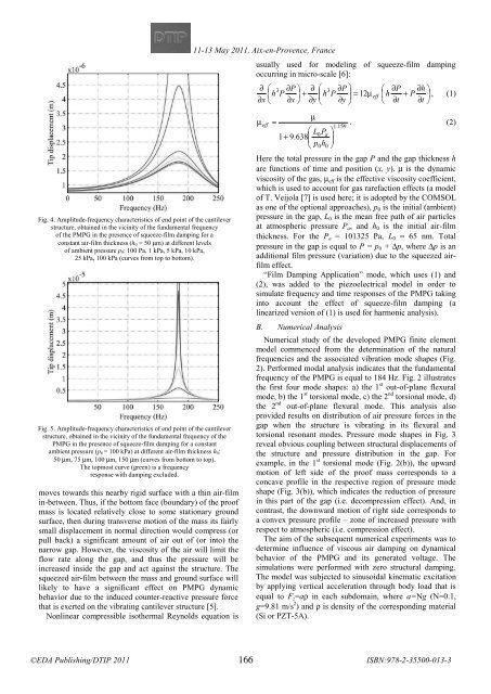
Fig. 4. Amplitude-frequency characteristics of end point of the cantilever<br />
structure, obtained in the vicinity of the fundamental frequency<br />
of the PMPG in the presence of squeeze-film damping for a<br />
constant air-film thickness (h 0 = 50 μm) at different levels<br />
of ambient pressure p 0: 100 Pa, 1 kPa, 5 kPa, 10 kPa,<br />
25 kPa, 100 kPa (curves from top to bottom).<br />
Fig. 5. Amplitude-frequency characteristics of end point of the cantilever<br />
structure, obtained in the vicinity of the fundamental frequency of the<br />
PMPG in the presence of squeeze-film damping for a constant<br />
ambient pressure (p 0 = 100 kPa) at different air-film thickness h 0:<br />
50 μm, 75 μm, 100 μm, 150 μm (curves from bottom to top).<br />
The topmost curve (green) is a frequency<br />
response with damping excluded.<br />
moves towards this nearby rigid surface with a thin air-film<br />
in-between. Thus, if the bottom face (boundary) of the proof<br />
mass is located relatively close to some stationary ground<br />
surface, then during transverse motion of the mass its fairly<br />
small displacement in normal direction would compress (or<br />
pull back) a significant amount of air out of (or into) the<br />
narrow gap. However, the viscosity of the air will limit the<br />
flow rate along the gap, and thus the pressure will be<br />
increased inside the gap and act against the structure. The<br />
squeezed air-film between the mass and ground surface will<br />
likely to have a significant effect on PMPG dynamic<br />
behavior due to the induced counter-reactive pressure force<br />
that is exerted on the vibrating cantilever structure [5].<br />
Nonlinear compressible isothermal Reynolds equation is<br />
11-13 May 2011, Aix-en-Provence, France<br />
<br />
usually used for modeling of squeeze-film damping<br />
occurring in micro-scale [6]:<br />
∂ ⎛ 3 ∂P<br />
⎞ ∂ ⎛ 3 ∂P<br />
⎞ ⎛ ∂P<br />
∂h<br />
⎞<br />
⎜ Ph ⎟ +<br />
⎜ Ph<br />
⎟ 12μ=<br />
eff ⎜h<br />
+ P ⎟ , (1)<br />
∂x<br />
⎝ ∂ ⎠ ∂yx<br />
⎝ ∂<br />
⎠ ⎝ ∂t<br />
∂t<br />
⎠<br />
μ<br />
eff =μ . (2)<br />
1.159<br />
⎛<br />
0PL<br />
⎞<br />
1+<br />
9.638<br />
⎜ a<br />
⎟<br />
⎝ hp 00 ⎠<br />
Here the total pressure in the gap P and the gap thickness h<br />
are functions of time and position (x, y). μ is the dynamic<br />
viscosity of the gas, μ eff is the effective viscosity coefficient,<br />
which is used to account for gas rarefaction effects (a model<br />
of T. Veijola [7] is used here; it is adopted by the COMSOL<br />
as one of the optional approaches), p 0 is the initial (ambient)<br />
pressure in the gap, L 0 is the mean free path of air particles<br />
at atmospheric pressure P a , and h 0 is the initial air-film<br />
thickness. For the P a = 101325 Pa, L 0 ≈ 65 nm. Total<br />
pressure in the gap is equal to P = p 0 + Δp, where Δp is an<br />
additional film pressure (variation) due to the squeezed airfilm<br />
effect.<br />
“Film Damping Application” mode, which uses (1) and<br />
(2), was added to the piezoelectrical model in order to<br />
simulate frequency and time responses of the PMPG taking<br />
into account the effect of squeeze-film damping (a<br />
linearized version of (1) is used for harmonic analysis).<br />
B. Numerical Analysis<br />
Numerical study of the developed PMPG finite element<br />
model commenced from the determination of the natural<br />
frequencies and the associated vibration mode shapes (Fig.<br />
2). Performed modal analysis indicates that the fundamental<br />
frequency of the PMPG is equal to 184 Hz. Fig. 2 illustrates<br />
the first four mode shapes: a) the 1 st out-of-plane flexural<br />
mode, b) the 1 st torsional mode, c) the 2 nd torsional mode, d)<br />
the 2 nd out-of-plane flexural mode. This analysis also<br />
provided results on distribution of air pressure forces in the<br />
gap when the structure is vibrating in its flexural and<br />
torsional resonant modes. Pressure mode shapes in Fig. 3<br />
reveal obvious coupling between structural displacements of<br />
the structure and pressure distribution in the gap. For<br />
example, in the 1 st torsional mode (Fig. 2(b)), the upward<br />
motion of left side of the proof mass corresponds to a<br />
concave profile in the respective region of pressure mode<br />
shape (Fig. 3(b)), which indicates the reduction of pressure<br />
in this part of the gap (i.e. decompression effect). And, in<br />
contrast, the downward motion of right side corresponds to<br />
a convex pressure profile – zone of increased pressure with<br />
respect to atmospheric (i.e. compression effect).<br />
The aim of the subsequent numerical experiments was to<br />
determine influence of viscous air damping on dynamical<br />
behavior of the PMPG and its generated voltage. The<br />
simulations were performed with zero structural damping.<br />
The model was subjected to sinusoidal kinematic excitation<br />
by applying vertical acceleration through body load that is<br />
equal to F z =aρ in each subdomain, where a=Ng (N=0.1,<br />
g=9.81 m/s 2 ) and ρ is density of the corresponding material<br />
(Si or PZT-5A).<br />
166


