

Online proceedings - EDA Publishing Association
Online proceedings - EDA Publishing Association
Online proceedings - EDA Publishing Association

Create successful ePaper yourself
Turn your PDF publications into a flip-book with our unique Google optimized e-Paper software.
11-13 <br />
May 2011, Aix-en-Provence, France<br />
Residual stress in the suspended membrane induced by the<br />
<br />
Here, q denotes the vector of modal amplitudes, φ<br />
pad , n<br />
the<br />
fabrication process has been taken into account by calibrating<br />
the fundamental eigenfrequency to the measured one.<br />
averaged modal shape factor for the n-th contact pad,<br />
The submodel for the electrostatic forces exerted by the<br />
ground electrode is derived in two steps. First, the electrostatic<br />
energy, which is stored between a single electrode finger and<br />
the membrane, is determined in terms of the modal amplitudes.<br />
Second, Lagrangian energy functionals are calculated for each<br />
eigenmode and are included as electrostatic actuation term in<br />
the respective eigenmode equation of the mechanical model.<br />
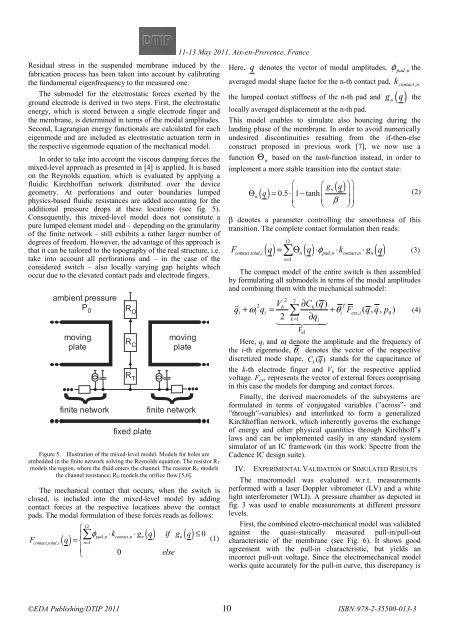
In order to take into account the viscous damping forces the<br />
mixed-level approach as presented in [4] is applied. It is based<br />
on the Reynolds equation, which is evaluated by applying a<br />
fluidic Kirchhoffian network distributed over the device<br />
geometry. At perforations and outer boundaries lumped<br />
physics-based fluidic resistances are added accounting for the<br />
additional pressure drops at these locations (see fig. 5).<br />
Consequently, this mixed-level model does not constitute a<br />
pure lumped element model and – depending on the granularity<br />
of the finite network – still exhibits a rather larger number of<br />
degrees of freedom. However, the advantage of this approach is<br />
that it can be tailored to the topography of the real structure, i.e.<br />
take into account all perforations and – in the case of the<br />
considered switch – also locally varying gap heights which<br />
occur due to the elevated contact pads and electrode fingers.<br />
ambient pressure<br />
P 0<br />
moving<br />
plate<br />
{<br />
finite network<br />
R O<br />
R C<br />
R T<br />
fixed plate<br />
moving<br />
plate<br />
{<br />
finite network<br />
Figure 5. Illustration of the mixed-level model. Models for holes are<br />
embedded in the finite network solving the Reynolds equation. The resistor R T<br />
models the region, where the fluid enters the channel. The resistor R C models<br />
the channel resistance; R O models the orifice flow [5,6].<br />
The mechanical contact that occurs, when the switch is<br />
closed, is included into the mixed-level model by adding<br />
contact forces at the respective locations above the contact<br />
pads. The modal formulation of these forces reads as follows:<br />
12<br />
⎧<br />
⎪<br />
( )<br />
∑ φpad , n<br />
⋅kcontact , n<br />
⋅gn ( q) if gn<br />
( q)<br />
≤0<br />
Fcontact, total,<br />
i<br />
q = ⎨ (1)<br />
n=<br />
1<br />
⎪⎩ 0 else<br />
k<br />
contact,<br />
n<br />
the lumped contact stiffness of the n-th pad and gn<br />
( )<br />
q the<br />
locally averaged displacement at the n-th pad.<br />
This model enables to simulate also bouncing during the<br />
landing phase of the membrane. In order to avoid numerically<br />
undesired discontinuities resulting from the if-then-else<br />
construct proposed in previous work [7], we now use a<br />
function Θ<br />
n<br />
based on the tanh-function instead, in order to<br />
implement a more stable transition into the contact state:<br />
⎛ ⎛ gn<br />
Θ<br />
n ( q)<br />
= 0.5⋅⎜1−tanh<br />
⎜<br />
⎜ ⎜ β<br />
⎝ ⎝<br />
( q)<br />
⎞⎞<br />
⎟⎟<br />
⎟⎟<br />
⎠⎠<br />
β denotes a parameter controlling the smoothness of this<br />
transition. The complete contact formulation then reads:<br />
12<br />
( ) = Θ ( ) ⋅φ<br />
⋅ ⋅ ( )<br />
F q ∑ q k g q (3)<br />
contact , total , i n pad , n contact , n n<br />
n=<br />
1<br />
The compact model of the entire switch is then assembled<br />
by formulating all submodels in terms of the modal amplitudes<br />
and combining them with the mechanical submodel:<br />
2 7<br />
2 Vb<br />
∂Ck( q)<br />
T<br />
i<br />
+ ωi i<br />
= ∑ + θi 2 k = 1 ∂qi<br />
<br />
ext, i<br />
<br />
0<br />
F el<br />
q<br />
q F ( qq , , p)<br />
Here, q i and ω i denote the amplitude and the frequency of<br />
the i-th eigenmode, θ i<br />
denotes the vector of the respective<br />
discretized mode shape, Ck<br />
( q ) stands for the capacitance of<br />
the k-th electrode finger and V k for the respective applied<br />
voltage. F ext represents the vector of external forces comprising<br />
in this case the models for damping and contact forces.<br />
Finally, the derived macromodels of the subsystems are<br />
formulated in terms of conjugated variables (”across”- and<br />
”through”-variables) and interlinked to form a generalized<br />
Kirchhoffian network, which inherently governs the exchange<br />
of energy and other physical quantities through Kirchhoff’s<br />
laws and can be implemented easily in any standard system<br />
simulator of an IC framework (in this work: Spectre from the<br />
Cadence IC design suite).<br />
IV. EXPERIMENTAL VALIDATION OF SIMULATED RESULTS<br />
The macromodel was evaluated w.r.t. measurements<br />
performed with a laser Doppler vibrometer (LV) and a white<br />
light interferometer (WLI). A pressure chamber as depicted in<br />
fig. 3 was used to enable measurements at different pressure<br />
levels.<br />
First, the combined electro-mechanical model was validated<br />
against the quasi-statically measured pull-in/pull-out<br />
characteristic of the membrane (see Fig. 6). It shows good<br />
agreement with the pull-in characteristic, but yields an<br />
incorrect pull-out voltage. Since the electromechanical model<br />
works quite accurately for the pull-in curve, this discrepancy is<br />
(2)<br />
(4)<br />
10


