

Online proceedings - EDA Publishing Association
Online proceedings - EDA Publishing Association
Online proceedings - EDA Publishing Association

You also want an ePaper? Increase the reach of your titles
YUMPU automatically turns print PDFs into web optimized ePapers that Google loves.
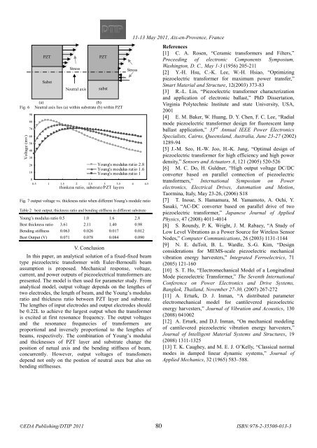
Fig. 6<br />
Voltage (mv)<br />
90<br />
80<br />
70<br />
60<br />
50<br />
40<br />
30<br />
20<br />
10<br />
0<br />
PZT<br />
Subst<br />
rate<br />
Stress<br />
Neutral axis<br />
PZT<br />
subst<br />
rate<br />
(a)<br />
(b)<br />
Neutral axis lies (a) within substrate (b) within PZT<br />
0.5 1 1.5 2 2.5 3 3.5 4 4.5<br />
thinkess ratio, substrate/PZT layers<br />
Fig. 7 output voltage vs. thickness ratio when different Young’s module ratio<br />
Table 2 best output, thickness ratio and bending stiffness in different substrate<br />
Young’s modulus ratio 0.5 1.0 1.6 2.8<br />
Best thickness ratio 3.61 2.11 1.40 0.98<br />
Bending stiffness 0.063 0.026 0.017 0.012<br />
Best Output (V) 0.071 0.078 0.084 0.090<br />
V. Conclusion<br />
Young's modulus ratio 2.8<br />
Young's modulus ratio 1.6<br />
Young's modulus ratio 1<br />
In this paper, an analytical solution of a fixed-fixed beam<br />
type piezoelectric transformer with Euler-Bernoulli beam<br />
assumption is proposed. Mechanical response, voltage,<br />
current, and power outputs of piezoelectrical transformers are<br />
presented. The model is then used for parameter study. From<br />
analytical model, output voltage depends on the lengthes of<br />
two electrodes, the length of beam, and the Young’s modulus<br />
ratio and thickness ratio between PZT layer and substrate.<br />
The lengthes of input electrodes and output electrodes should<br />
be 0.22L to achieve the largest output when the transformer<br />
is excited at first resonance frequency. The output voltages<br />
and the resonance frequnecies of transformers are<br />
proportional and inversely proportional to the lengthes of<br />
beams, respectively. The combination of Young’s modului<br />
and thicknesses of PZT layer and substrate change the<br />
position of netual axis and the bending stiffness of beam,<br />
concurrently. However, output voltages of transfomers<br />
depend not only on the postion of neutral axes but also on<br />
bending stiffnesses.<br />
11-13 May 2011, Aix-en-Provence, France<br />
<br />
References<br />
[1] C. A. Rosen, “Ceramic transformers and Filters,”<br />
Proceeding of electronic Components Symposium,<br />
Washington, D. C., May 1-3 (1956) 205-211<br />
Stress<br />
[2] Y.-H. Hsu, C.-K. Lee, W.-H. Hsiao, “Optimizing<br />
piezoelectric transformer for maximum power transfer,”<br />
Smart Material and Structure, 12(2003) 373-83<br />
[3] R.-L. Lin, “Piezoelectric transformer characterization<br />
and application of electronic ballast,” PhD Dissertation,<br />
Virginia Polytechnic Institute and state University, USA,<br />
2001<br />
[4] E. M. Baker, W. Huang, D. Y. Chen, F. C. Lee, “Radial<br />
mode piezoelectric transformer design for fluorescent lamp<br />
ballast application,” 33 rd Annual IEEE Power Electronics<br />
Specialists, Cairns, Queensland, Australia, June 23-27 (2002)<br />
1289-94<br />
[5] J.-M. Seo, H.-W. Joo, H.-K. Jung, “Optimal design of<br />
piezoelectric transformer for high efficiency and high power<br />
density,” Sensors and Actuators A, 121 (2005) 520-526<br />
[6] M. C. Do, H. Guldner, “High output voltage DC/DC<br />
converter based on parallel connection of piezoelectric<br />
transformers,” International Symposium on Power<br />
electronics, Electrical Drives, Automation and Motion,<br />
Taormina, Italy, May 23-26, (2006) S18<br />
[7] T. Inoue, S. Hamamura, M. Yamamoto, A. Ochi, Y.<br />
Sasaki, “AC-DC converter based on parallel drive of two<br />
piezoelectric transformer,” Japanese Journal of Applied<br />
Physics, 47 (2008) 4011-4014<br />
[8] S. Roundy, P. K. Wright, J. M. Rabaey, “A Study of<br />
Low Level Vibrations as a Power Source for Wireless Sensor<br />
Nodes,” Computer Communications, 26 (2003) 1131-1144<br />
[9] N. E. duToit, B. L. Wardle, S.-G. Kim, “Design<br />
considerations for MEMS-scale piezoelectric mechanical<br />
vibration energy harvesters,” Integrated Ferroelectrics, 71<br />
(2005) 121-160<br />
[10] S. T. Ho, “Electromechanical Model of a Longitudinal<br />
Mode piezoelectric Transformer,” The Seventh International<br />
Conference on Power Electronics and Drive Systems,<br />
Bangkok, Thailand, November 27-30, (2007) 267-272<br />
[11] A. Erturk, D. J. Inman, “A distributed parameter<br />
electromechanical model for cantilevered piezoelectric<br />
energy harvesters,” Journal of Vibration and Acoustics, 130<br />
(2008) 041002<br />
[12] A. Erturk, and D.J. Inman, “On mechanical modeling<br />
of cantilevered piezoelectric vibration energy harvesters,”<br />
Journal of Intelligent Material Systems and Structures, 19<br />
(2008) 1311-1325<br />
[13] T. K. Caughey, and M. E. J. O’Kelly, “Classical normal<br />
modes in damped linear dynamic systems,” Journal of<br />
Applied Mechanics, 32 (1965) 583–588.<br />
80


