

Online proceedings - EDA Publishing Association
Online proceedings - EDA Publishing Association
Online proceedings - EDA Publishing Association

You also want an ePaper? Increase the reach of your titles
YUMPU automatically turns print PDFs into web optimized ePapers that Google loves.
coupling rotation movement in the Y and X directions as shown<br />
in the X, Y, and Z components in Fig. 5. The area on the back of<br />
the cylinder also flows rotationally in the Z direction. Rotation<br />
in the Y direction was also generated at the end of the sensing<br />
field. The flow chart also reveals the chaotic flow effect that<br />
was generated in the microenvironment at this stage<br />
(a)<br />
(c)<br />
(d)<br />
Fig. 4 Vortices when (a) hc =300 m (b) hc = 400 m (c) hc = 500 m (d) hc =<br />
600 m<br />
(a)<br />
(b)<br />
(b)<br />
11-13 <br />
May, 2011, Aix-en-Provence, France<br />
<br />
PDMS solidifies after evacuation and heating. PDMS can be<br />
removed from the inserts. Additionally, the atmospheric<br />
pressure plasma can modify the convection channel and the<br />
PDMS surface of the substrate. The parameter 0.5 Torr, 29.6<br />
Watt, and 15 min~20 min represents pressure, plasma<br />
efficiency, and surface modification time. The microchannel<br />
was then connected with the substrate after PDMS was used to<br />
implement the surface modification procedure.<br />
3.2.2 Fluorescence streamline<br />
For this part of the study, we utilized fluorescent particles<br />
to examine the actual streamline condition of the microfluidics.<br />
The fluorescent particles used had a grain size of 10m,<br />
filtering band was between 460 and 490 nm. An Olympus IX71<br />
fluorescent microscope was used in a dark environment to<br />
provide the optical band that excites the particles, allowing the<br />
fluorescent particles to generate fluorescence automatically<br />
after photo-excitation in a specific band. When the fluorescent<br />
particles move with the streamline in the channel, the trajectory<br />
of the fluorescent particles reveals the actual streamline<br />
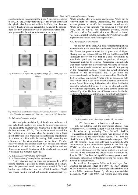
condition of the microfluidics. Fig. 6 (a) shows the<br />
experimental results of the fluorescent streamline. The fluid in<br />
the figure rotates in direction Y when entering the sensing field<br />
from the left. This is due to the height difference between the<br />
bottom face of the sensing field and the inlet. When the fluidics<br />
passes the cylindrical structure, it reveals an identical result to<br />
the estimation implemented by the finite element simulation<br />
software Fig. 6(b). The flow rate difference causes the fluid to<br />
rotate toward direction Z at the back of the cylindrical structure.<br />
(c)<br />
Fig. 5 Simulation result when flow rate is 0.614 μm/s(a)Vorticity, x component<br />
(b)Vorticity, y component(c)Vorticity, z component(d)Streamline<br />
3.2 Microenvironment design<br />
After analysis simulation by finite element software, a 1<br />
mm cylindrical structure was added to the microenvironment.<br />
The height of the structure was 500 m while the rate of flow in<br />
the inlet area was 1500 ml / hr . The simulation result showed that<br />
the vortices were generated when the structure had a large<br />
speed difference. This phenomenon creates more opportunities<br />
for viruses to collide with the sensing field, enhancing the<br />
efficiency of the virus attachment to the field. We also<br />
discovered that a relationship might exist between the strength<br />
distribution of curl at the back of the cylinder and the<br />
fluorescence strength distribution of the attachment experiment.<br />
We discuss this further in Section 5.<br />
3.3 Fluorescence streamline experiment<br />
3.3.1 Fabrication of microfluidics environment<br />
Firstly, stainless steel or brass was processed by a CNC<br />
milling machine to produce the inserts designed in the study.<br />
After the processed metal inserts were cleaned, PDMS and<br />
hardener were fully mixed in a ratio of 10:1, and then PDMS<br />
was poured into the channel and substrate inserts respectively.<br />
(d)<br />
(a)<br />
Fig. 6 Streamlines by(a)fluorescent particles (b)simulation<br />
IV. FABRICATION OF RECOGNITION LAYERS<br />
First, the substrate and the microfluidic channel were<br />
fabricated by PDMS casting. A layer of Au film was deposited<br />
on the substrate by sputtering. Then, 20 mM 11-MUA<br />
(11-mercaptoundecanoic acid) solution was injected on the<br />
sensor surface by the microfluidics system. This links the<br />
11-MUA with gold films as self-assembled monolayers. EDC<br />
and NHS solutions (molar ratio, 2:1) were then injected on the<br />
sensor surface by the microfluidics system. In the final step,<br />
TYMV particles with fluorescent particles (NCD4) in the<br />
buffer were introduced over the sensor surface at a different<br />
flow rate. In the meantime, the sensor surface was rinsed and<br />
dried in FPLC (Fast Protein Liquid Chromatography) to avoid<br />
nonspecific adhesion. A confocal microscope was then used to<br />
monitor the sensor surface.<br />
To avoid the low-quality MUA molecular layer from<br />
affecting the adhesion effect of TYMV, the study adopted<br />
NCD-4 fluorescent particles as the sample and carried out tests<br />
on the MUA molecular layers. By adopting a cross-linker<br />
mechanism, NCD-4 and MUA can respond and bond more<br />
(b)<br />
369


